
Grabbing equipment for intelligent machine manufacturing

A technology of intelligent machinery and equipment, applied in the direction of manipulators, manufacturing tools, chucks, etc., can solve the problem that the system is difficult to complete tasks accurately and efficiently, and achieve the effect of accurately and efficiently grabbing workpieces

Inactive Publication Date: 2020-03-24
清远海帆智能科技有限公司
View PDF5 Cites 4 Cited by
  • Summary
  • Abstract
  • Description
  • Claims
  • Application Information

AI Technical Summary

Problems solved by technology

[0002] Since the birth of the first modern robotic arm in the 1950s, the robotic arm has developed into a precise and reliable mechanical device with redundant degrees of freedom, and has played an important role in various industrial productions. An important role, this type of robotic arm can mechanically complete fixed actions or run precisely according to a fixed trajectory, but in the fields of medical treatment or exploration, due to the complex and changeable conditions of the object and the surrounding environment, it is impossible for us to In industrial production, the movements of the robotic arm are designed and arranged in advance, so that the traditional robotic arm cannot handle the current work. Therefore, it is very important whether the robotic arm can handle specific objects by itself.
[0003] At present, similar robotic arm grasping systems on the market mainly measure and calculate the coordinates of the target to be grasped, while the attitude of the gripper is basically tried through experience. It is difficult for this type of system to complete the task accurately and efficiently.

Method used


Image

  • Grabbing equipment for intelligent machine manufacturing
  • Grabbing equipment for intelligent machine manufacturing
  • Grabbing equipment for intelligent machine manufacturing

Examples


Embodiment Construction

[0020] The technical solutions in the embodiments of the present invention will be clearly and completely described below. Obviously, the described embodiments are only some of the embodiments of the present invention, but not all of them. Based on the embodiments of the present invention, all other embodiments obtained by persons of ordinary skill in the art without making creative efforts belong to the protection scope of the present invention.

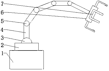
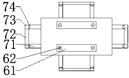
[0021] see Figure 1~3 , in an embodiment of the present invention, an intelligent mechanical manufacturing grabbing device includes a base 1, a turntable 2, a rotating member 3, a mechanical arm 4, a mechanical joint 5, a manipulator 6, a gripper 7, an external power cord 11, and a switching power supply 12 , low-voltage transmission line 13, signal line 14, industrial computer 15, binocular camera 61, camera lens 62, telescoping rod 71, connecting rod 72, pressure plate 73 and pressure sensor 74, turntable 2 is installed on the de...


PUM


Abstract

The invention discloses grabbing equipment for intelligent machine manufacturing. The grabbing equipment comprises a base, a rotary table, a rotary piece, mechanical arms, mechanical joints, a manipulator, clamping jaws, an external power line, a switching power supply, a low-voltage transmission line, a signal line, an industrial personal computer, binocular cameras, camera lenses, a telescopic rod, a connecting rod, a pressing plate and a pressure sensor. The rotary table is installed on the base. The rotary table drives the rotary piece, a mechanical arm is fixed to the rotary piece, the mechanical arm is connected with mechanical arms of different specifications through the mechanical joints, the mechanical arms and the mechanical joints are connected in sequence, one end of the mechanical arm at a tail end is installed in the center of a bottom face of the manipulator, and the clamping jaws are installed on four side faces of the manipulator. The distance between a to-be-grabbed workpiece and the manipulator is determined through shooting of the binocular cameras and operation of the industrial personal computer, then the manipulator is moved through movement of the mechanicalarms, finally the grabbing of the to-be-grabbed workpiece is completed, and the purpose of accurately and efficiently grabbing the workpiece can be achieved.

Description

technical field [0001] The invention relates to the field of intelligent manufacturing, in particular to an intelligent mechanical manufacturing grabbing device. Background technique [0002] Since the birth of the first modern robotic arm in the 1950s, the robotic arm has developed into a precise and reliable mechanical device with redundant degrees of freedom, and has played an important role in various industrial productions. An important role, this type of robotic arm can mechanically complete fixed actions or run precisely according to a fixed trajectory, but in the fields of medical treatment or exploration, due to the complex and changeable conditions of the object and the surrounding environment, it is impossible for us to In industrial production, the movements of the robotic arm are designed and arranged in advance, so that the traditional robotic arm is not competent for the current work, so whether the robotic arm can handle specific objects by itself becomes ver...

Claims


Application Information

Patent Timeline
IPC IPC(8): B25J13/08B25J15/02B25J15/08B25J19/02
CPCB25J13/081B25J15/02B25J15/08B25J19/023
Inventor 王萍
Owner 清远海帆智能科技有限公司
Learn More