
Pure-magnetic-drive gas booster

A gas pressurization and magnetic drive technology, applied in the field of pressure machinery, can solve problems such as complex structure, large load and frictional resistance, and achieve the effects of reducing friction, increasing pressure, and improving efficiency

Pending Publication Date: 2020-02-18
李迦怡
View PDF2 Cites 2 Cited by
  • Summary
  • Abstract
  • Description
  • Claims
  • Application Information

AI Technical Summary

Problems solved by technology

Compared with the compressors that use the driving device to drive the rocker arm to drive the piston to reciprocate, the above two solutions have made great progress, but there are still complex structures, and the piston is driven by the connecting rod. Load and friction Therefore, it is an urgent need to develop a new magnetic drive gas booster

Method used


Image

  • Pure-magnetic-drive gas booster
  • Pure-magnetic-drive gas booster
  • Pure-magnetic-drive gas booster

Examples


Embodiment Construction

[0030] The present invention will be described in detail below in conjunction with the accompanying drawings. The description in this part is only exemplary and explanatory, and should not have any limiting effect on the protection scope of the present invention. In addition, according to the description of this document, those skilled in the art can make corresponding combinations of the features in the embodiments and different embodiments in this document. The term "gas" used includes gaseous substances, liquid substances, or consists of liquid substances and gaseous substances. mixture.

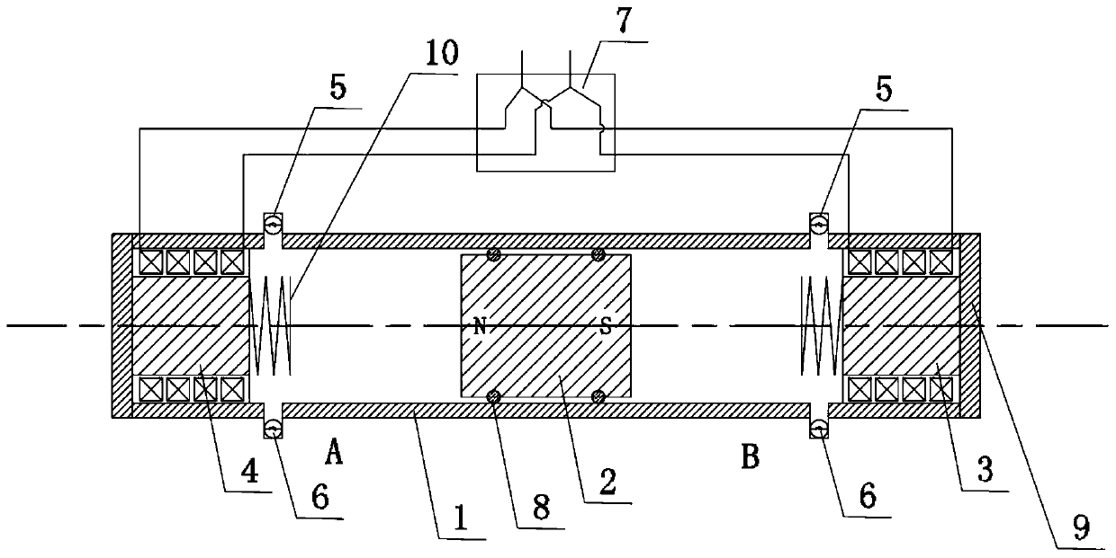
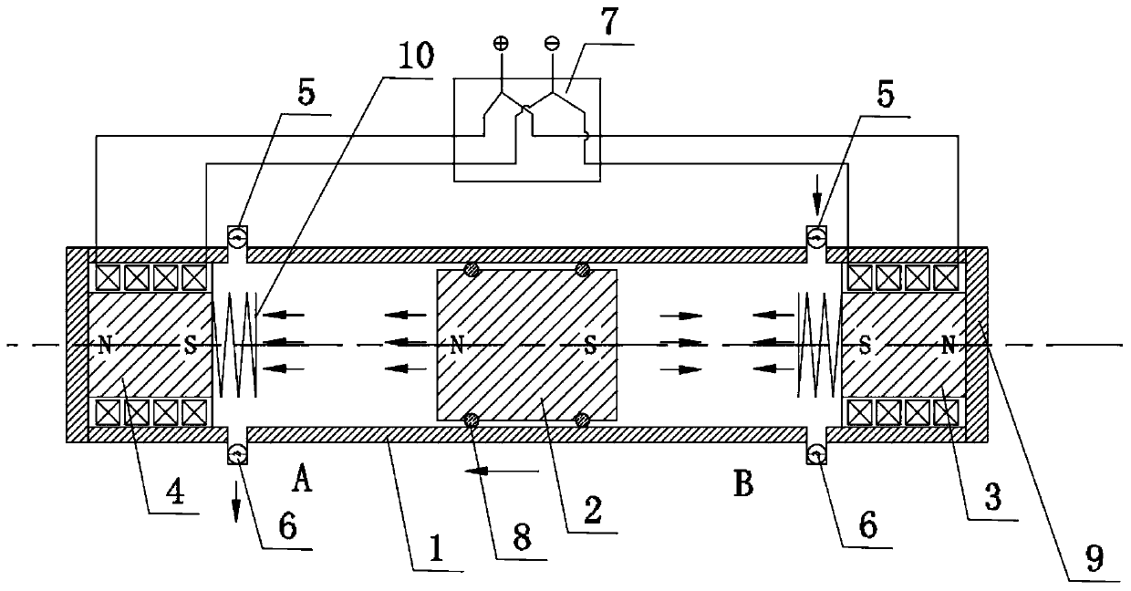
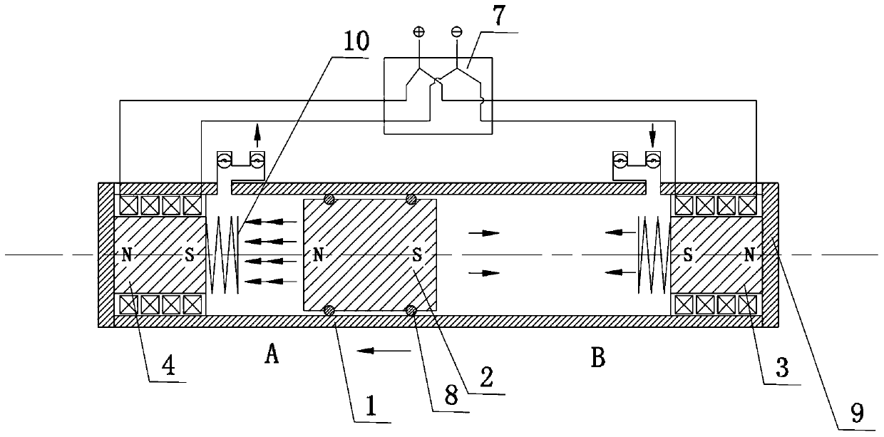
[0031] Embodiments of the present invention are as follows, as figure 1 As shown, a pure magnetic drive gas booster includes a cylinder body 1 and a piston 2 in the cylinder body 1. Both ends of the cylinder body 1 are provided with a plugging head 3, and the piston 2 is placed in the cylinder body 1. , the piston 2 is a permanent magnet piston, and the two plugging heads 3 are electroma...


PUM


Abstract

The invention discloses a pure-magnetic-drive gas booster which comprises a cylinder body and a piston in the cylinder body. The pure-magnetic-drive gas booster is characterized in that the two ends of the cylinder body are equipped with plugging heads, wherein a piston is arranged in the cylinder body, the piston is a permanent magnet piston, at least one of the two plugging heads is an electromagnetic driver, the two end parts of the cylinder body are each equipped with a one-way gas inlet and a one-way gas outlet, which define a group; after the electromagnetic driver on the end part of thecylinder body is energized, a corresponding magnetic pole is formed to axially apply force, and the magnetic pole is matched with a magnetic pole of the permanent magnet piston to drive the piston tomove, so that gas enters from the one-way gas inlet, and pressurized gas is output from the one-way gas outlet.

Description

technical field [0001] The invention relates to the field of pressure machinery, in particular to a pure magnetic drive gas booster. Background technique [0002] At present, a large part of the existing gas compressors are positive displacement gas compressors, whose working principle is to close a fixed amount of gas in the compression chamber, mechanically reduce the volume occupied by the gas to compress the gas, and compress the compressed gas Gas in and out. The increase in gas pressure corresponds to the decrease in volume of the space occupied by the same amount of gas. The term "gas" as used in this specification includes gaseous substances, liquid substances or mixtures of liquid and gaseous substances. Most positive displacement compressors mechanically reduce the volume occupied by the gas by using rotating parts, which are often driven the device drives the rocker arm to reciprocate the piston, and each time the piston moves into the compression chamber, the p...

Claims


Application Information

Patent Timeline
IPC IPC(8): F04B35/04F04B31/00F04B25/00F04B27/00F04B39/00F04B39/10F04B41/02F04B49/06
CPCF04B25/005F04B27/005F04B31/00F04B35/04F04B39/0005F04B39/10F04B41/02F04B49/06
Inventor 李迦怡
Owner 李迦怡
Learn More