
Empennage assembling equipment

A technology for assembling equipment and tail fins, which is applied in metal processing equipment, metal processing, manufacturing tools, etc., can solve the problems of easy damage to the tail end surface of the missile body, easy screwing of tail fins, and low assembly efficiency, so as to avoid excessive rotation Or it is not rotated in place, it is convenient for alignment and the effect of improving production efficiency

Pending Publication Date: 2020-02-18
HUNAN JUNCHENG TECH
View PDF0 Cites 1 Cited by
  • Summary
  • Abstract
  • Description
  • Claims
  • Application Information

AI Technical Summary

Problems solved by technology

As shells are explosive items, manual assembly is dangerous to a certain extent, and the assembly efficiency is not high. The empennage is easy to be unscrewed or over-screwed, and it is easy to manually operate when the empennage is aligned with the threaded port at the tail end of the projectile. Damage to the surface of the tail end of the projectile

Method used


Image

  • Empennage assembling equipment
  • Empennage assembling equipment
  • Empennage assembling equipment

Examples


Embodiment 1

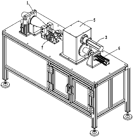
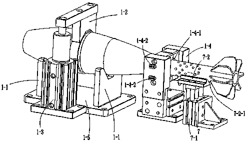
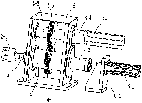
[0034] See Figure 1 to Figure 5 , The empennage assembly equipment of this embodiment includes body positioning tooling 1, empennage support base 7, floating wrench lever 2, driving mechanism 3, transmission sleeve 4, box body 5 and feed assembly 6.

[0035] Both the driving mechanism 3 and the transmission sleeve 4 are arranged in the box body 5 . The projectile positioning tool 1 positions and clamps the projectile. The empennage support base 7 is arranged between the transmission sleeve 4 and the body positioning tool 1, and the top of the empennage support base 7 is used for placing the empennage. The driving mechanism 3 drives the transmission sleeve 4 to rotate in the circumferential direction. The floating wrench rod 2 is slidably arranged in the transmission sleeve 4 in the axial direction, and is fixed relative to the transmission sleeve 4 in the circumferential direction. The front end of the floating wrench bar 2 is provided with an empennage wrench 2-1. The fl...


PUM


Abstract

The invention discloses empennage assembling equipment. The empennage assembling equipment comprises a projectile positioning tool, an empennage supporting seat, a floating wrench rod, a driving mechanism, a transmission sleeve, a box body and a feeding assembly. Both the driving mechanism and the transmission sleeve are arranged in the box body. The projectile positioning tool is used for positioning and clamping a projectile. The empennage supporting seat is arranged between the transmission sleeve and the projectile positioning tool. The top of the empennage supporting seat is used for placing an empennage. The driving mechanism drives the transmission sleeve to rotate in the circumferential direction. The floating wrench rod is axially slidably arranged in the transmission sleeve and is circumferentially fixed opposite to the transmission sleeve. An empennage wrench is arranged at the front end of the floating wrench rod. The floating wrench rod moves axially under the driving of the feeding assembly, so that the empennage wrench is matched with the empennage. According to the empennage assembling equipment, the projectile is positioned by the projectile positioning tool, the feeding assembly pushes the floating wrench rod to move, the empennage wrench is matched with the empennage, the driving mechanism drives the empennage to rotate, the empennage is screwed with the projectile, automatic projectile empennage assembling work is achieved, and the production efficiency is improved.

Description

technical field [0001] The invention relates to the field of shell empennage assembly, in particular to an empennage assembly device. Background technique [0002] At present, the empennage and the body of the projectile are separate structures, such as mortars, which need to be conveniently processed during production, and finally the body and the empennage are assembled. In the prior art, the empennage The assembly is manual assembly, the projectile is placed on the positioning table, and the tail is screwed into the threaded port at the end of the projectile by a special wrench. As shells are explosive items, manual assembly is dangerous to a certain extent, and the assembly efficiency is not high. The empennage is easy to be unscrewed or over-screwed, and it is easy to manually operate when the empennage is aligned with the threaded port at the tail end of the projectile. Damage to the surface of the tail end of the projectile. Contents of the invention [0003] The ...

Claims


Application Information

Patent Timeline
Patent Type & Authority Applications(China)
IPC IPC(8): B23P19/00
CPCB23P19/00
Inventor 刘军
Owner HUNAN JUNCHENG TECH
Learn More