Brake disc sand core robot fixture

A robotic fixture and brake disc technology, which is applied to devices and coatings that apply liquid to the surface, can solve the problems of long time and reduced efficiency, and achieve the effects of low production cost, improved production efficiency, and uniform dip coating.

Active Publication Date: 2021-04-06
SUZHOU SUNSHINE MACHINERY MFR
View PDF22 Cites 0 Cited by
  • Summary
  • Abstract
  • Description
  • Claims
  • Application Information

AI Technical Summary

Problems solved by technology

[0006] Although the work efficiency has been greatly improved in this way, after the sand core is pulled to the liquid surface before the third branch arm 22 rotates to the initial position, it will start to drip the remaining dipping liquid, and this process needs to be slow. Slowly wait for the dripping of the residual dipping liquid, which takes a long time, resulting in a decrease in efficiency

Method used


Image

  • Brake disc sand core robot fixture
  • Brake disc sand core robot fixture
  • Brake disc sand core robot fixture

Examples


Embodiment Construction

[0032] This specific embodiment is only an explanation of the present invention, and it is not a limitation of the present invention. Those skilled in the art can make modifications to this embodiment without creative contribution as required after reading this specification, but as long as they are within the rights of the present invention All claims are protected by patent law.

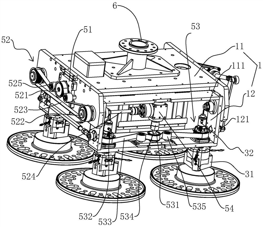
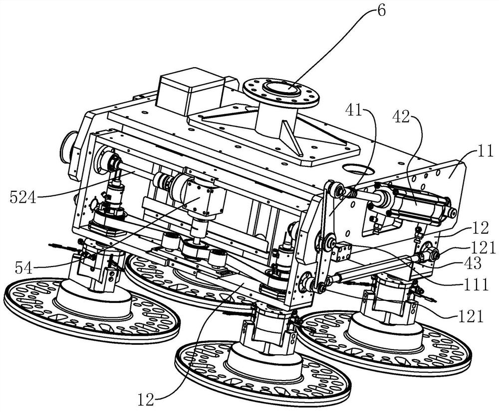
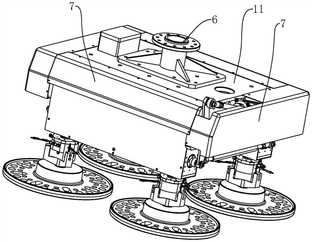
[0033] A brake disc sand core robot fixture, such as figure 1 , including a main frame 1, a workpiece clamping unit installed on the main frame 1, the workpiece clamping unit includes a sand core clamp 31, a main shaft 32 that is fixedly connected with the sand core clamp 31 and can rotate relative to the main frame 1, and the rotation of the main shaft 32 The axis is vertically arranged and connected to the power mechanism that drives the main shaft 32 to rotate.

[0034] Such as figure 1 , The main frame 1 includes a fixed frame 11 and a movable frame 12, two movable frames 12 are arranged symm...


PUM


Abstract

The invention discloses a brake disc sand core robot clamp, which comprises a main frame and a workpiece clamping unit installed on the main frame. The workpiece clamping unit includes a sand core clamp, is fixedly connected with the sand core clamp and can be relatively A rotating main shaft, the rotation axis of which is vertically arranged and connected to a power mechanism that drives the main shaft to rotate. When the brake disc sand core robot fixture is used, it is connected to the manipulator, and the sand core fixture above it clamps the sand core through pneumatic control. The core moves up and comes out of the dipping liquid, and the main shaft is driven to rotate through the power mechanism. Since the main shaft and the sand core fixture are fixed, the sand core will also be driven to rotate, and the residual liquid above is quickly thrown off to complete the dip coating operation of a sand core. , Improve operating efficiency and ensure product quality.

Description

technical field [0001] The invention relates to the field of auto parts production, in particular to a brake disc sand core robot fixture. Background technique [0002] Brake discs and other components are widely used in the automobile manufacturing industry. The production of such castings requires a large number of sand cores. In order to ensure the quality of castings, many sand cores need to be dip-coated on the surface of the casting according to the process requirements, so as not to affect the positioning of the core assembly. [0003] The initial dip coating is mainly manual operation, the work efficiency is low, and the product quality is uncontrollable. [0004] In order to solve the above problems, the patent with the notification number CN208712072U discloses a dip-coating automatic lifting arm, which includes a bracket, a mounting platform and an arm body. The main body consists of a main arm and a sub-arm. The main arm is vertically fixed on the rotating seat,...

Claims


Application Information

Patent Timeline
Patent Type & Authority Patents(China)
IPC IPC(8): B05C13/02B05C11/10
CPCB05C11/1039B05C13/02
Inventor 虞峰严婷婷
Owner SUZHOU SUNSHINE MACHINERY MFR
Why Eureka
Try Eureka