An automatic detachment and hanging safety sling

A safe and spreader technology, applied in the direction of load hanging components, transportation and packaging

Active Publication Date: 2021-08-20
BEIJING INST OF CONSTR MECHANIZATION +2
View PDF4 Cites 0 Cited by
  • Summary
  • Abstract
  • Description
  • Claims
  • Application Information

AI Technical Summary

Problems solved by technology

[0004] The purpose of the present invention is to provide an automatic unhook safety spreader to solve the problem of automatic unhook and anti-off of the spreader

Method used


Image

  • An automatic detachment and hanging safety sling
  • An automatic detachment and hanging safety sling
  • An automatic detachment and hanging safety sling

Examples


Embodiment Construction

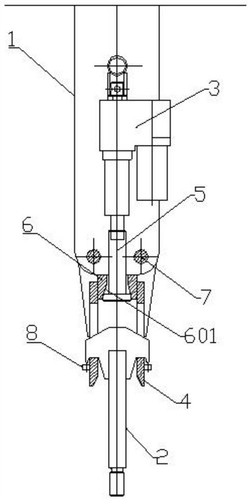
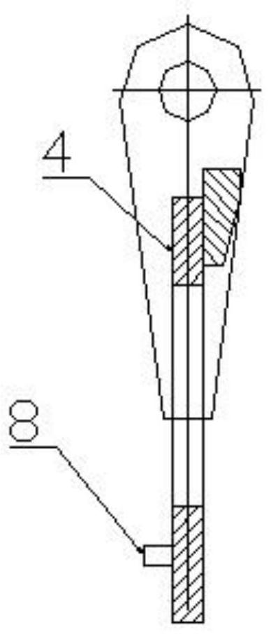
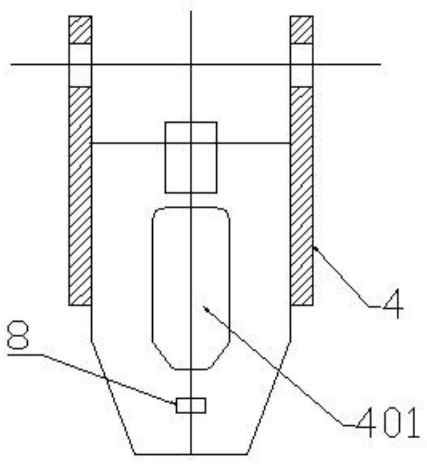
[0020] Such as figure 1 , 2 , 3, 4, and 5 show a specific embodiment of an automatic unhooking safety hanger, including a main body 1, a hanging nail 2 and a driving device 3 installed on the main body 1. The main body 1 is hinged with two hook plates 4 through the rotating shaft 7 at opposite positions, so that the two hook plates can rotate around the rotating shaft to realize the separation / closing of the lower ends of the two hook plates. The driving device 3 is used to drive the two hook plates 4 to turn over in the opposite direction to separate them. Specifically, the driving device 3 is an up and down driving device, and the telescopic end of the driving device 3 is equipped with a driving body 5. The driving device in the example used an electric push rod, and the driving body was installed on the rod end of the electric pushing rod, so that the driving device drove the driving body to move up and down. The inner sides of the two hook plates 4 are provided with a gu...


PUM


Abstract

The invention discloses an automatic lifting safety hanger, which comprises a main body, a hanging nail and a driving device arranged on the main body; two hook plates are hinged on the main body at opposite positions, and the two hook plates Both are provided with holes; the driving device is used to drive the two hook plates to turn in opposite directions to separate; the hook plates can be closed in the opposite direction under the action of their own gravity; both sides of the hanger nails are provided with wings There are downward protrusions on the edge of the flange plate. When the two hook plates are closed, the two flange plates are respectively inserted into the two holes. The protrusions can prevent the hook plate from slipping from the edge of the flange plate. out. The present invention drives the hook plate to open or allows the hook plate to be closed by a driving device. The hook plate has a hole, and the hanging nail has a flange plate. The flange plate is set to protrude downward. When the hook plate is closed, the flange plate enters the hole to realize the hook; and it can prevent false hanging and accidental unhooking.

Description

technical field [0001] The invention relates to the field of construction hoisting equipment, in particular to an automatic lifting safety hanger. Background technique [0002] At present, in the hoisting operation of building structural parts, the removal and hanging of the hook is usually done manually. Due to the large size of the components, ladder climbing operations are required, and the safety guarantee is poor and the efficiency is low. The use of automatic hook removal for hoisting operations can effectively improve the safety of component hoisting operations. [0003] Therefore, the present invention proposes a simple and reliable automatic detachment hanger form. Contents of the invention [0004] The purpose of the present invention is to provide an automatic unhanging safety spreader, which solves the problems of automatic unhanging and detachment of the spreader. [0005] In order to solve the problems of the technologies described above, the present invent...

Claims


Application Information

Patent Timeline
Patent Type & Authority Patents(China)
IPC IPC(8): B66C1/34
CPCB66C1/34
Inventor 罗文龙姚金柯陈赣平王涛史宏旻陈晓峰郑旭
Owner BEIJING INST OF CONSTR MECHANIZATION
Why Eureka
Try Eureka