
A Method of Improving Phase Accuracy of Vector Network Analyzer Scanning Test

A technology of vector network analysis and scan test, which is applied in the field of improving the phase accuracy of vector network analyzer scan test, can solve the problems of long signal passing time and large phase measurement error, and achieves the effect of simple data processing method

Active Publication Date: 2021-09-03
CHINA ELECTRONIS TECH INSTR CO LTD
View PDF5 Cites 0 Cited by
  • Summary
  • Abstract
  • Description
  • Claims
  • Application Information

AI Technical Summary

Problems solved by technology

When the DUT is relatively long, the signal passing time is relatively long, which will generate a relatively large phase measurement error

Method used


Image

  • A Method of Improving Phase Accuracy of Vector Network Analyzer Scanning Test
  • A Method of Improving Phase Accuracy of Vector Network Analyzer Scanning Test
  • A Method of Improving Phase Accuracy of Vector Network Analyzer Scanning Test

Examples


Embodiment Construction

[0035] The specific embodiment of the present invention will be further described below in conjunction with accompanying drawing and specific embodiment:

[0036] A method for improving the phase accuracy of a vector network analyzer scanning test. During the scanning measurement process, the frequency measurement of the intermediate frequency signal is carried out at the same time as the S21 phase measurement, and the time delay of the tested part is calculated through the frequency deviation. The measured initial measurement of the S21 phase is corrected. Specifically include the following steps:

[0037] Step 1: Find the frequency of the response intermediate frequency signal: During the scan test, perform fft transformation on the digitized response intermediate frequency signal, search for the maximum value of the transformed data, and the corresponding frequency is the frequency ω of the response intermediate frequency signal IFa ;

[0038] Step 2: According to the fre...


PUM


Abstract

The invention discloses a method for improving the phase accuracy of a vector network analyzer scanning test, and specifically relates to the technical field of vector network analyzer scanning measurement. In the scanning measurement process, the invention measures the frequency of the intermediate frequency signal while measuring the S21 phase, calculates the time delay of the measured part through the frequency deviation, and uses the time delay of the tested part to correct the measured initial measurement value of the S21 phase. The method can obtain the factors that affect the phase measurement result and eliminate the influence, and solve the problem that the existing measurement method has a large error in the phase result when the S21 measurement is performed on a long test piece.

Description

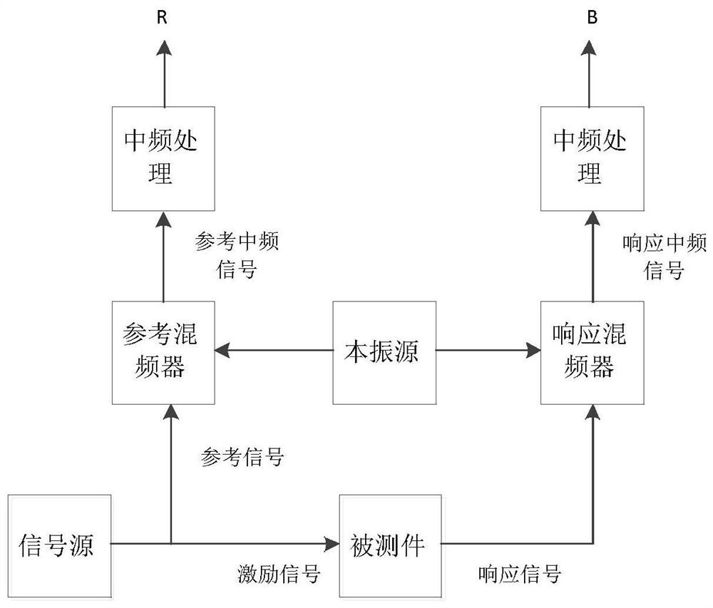
technical field [0001] The invention relates to the technical field of vector network analyzer scanning measurement, in particular to a method for improving the phase accuracy of vector network analyzer scanning test. Background technique [0002] A vector network analyzer is a microwave measuring instrument. It generates a microwave signal through a microwave signal source and divides it into two channels. One is used as a reference signal, and the other is used as an excitation signal. The excitation signal excites the DUT to generate a response signal. Both the reference signal and the response signal are mixed with the local oscillator signal generated by the local oscillator source through the mixer, and the frequency is reduced to an intermediate frequency signal with a lower frequency. After sampling and digital processing, the measurement results of the reference circuit R and the response circuit are obtained. Measurement result B. Calculate the ratio of B and R to...

Claims


Application Information

Patent Timeline
Patent Type & Authority Patents(China)
IPC IPC(8): G01R31/00
CPCG01R31/00G01S7/48G01S17/00
Inventor 许春卿梁胜利杨保国曹志英张庆龙陈恩刚杨玉斌刘丹孙胜凯刘涛邢宇辰
Owner CHINA ELECTRONIS TECH INSTR CO LTD
Learn More