
Terminal and camera lamp effect control method

A lighting effect control and camera technology, applied in the field of communication, can solve the problem of single function of the camera module

Active Publication Date: 2019-09-17
VIVO MOBILE COMM HANGZHOU CO LTD
View PDF7 Cites 2 Cited by
  • Summary
  • Abstract
  • Description
  • Claims
  • Application Information

AI Technical Summary

Problems solved by technology

[0003] Embodiments of the present invention provide a terminal and camera lighting effect control method to solve the problem of single function of the camera module in the prior art

Method used


Image

  • Terminal and camera lamp effect control method
  • Terminal and camera lamp effect control method
  • Terminal and camera lamp effect control method

Examples


Embodiment Construction

[0031] The following will clearly and completely describe the technical solutions in the embodiments of the present invention with reference to the accompanying drawings in the embodiments of the present invention. Obviously, the described embodiments are some of the embodiments of the present invention, but not all of them. Based on the embodiments of the present invention, all other embodiments obtained by persons of ordinary skill in the art without creative efforts fall within the protection scope of the present invention.

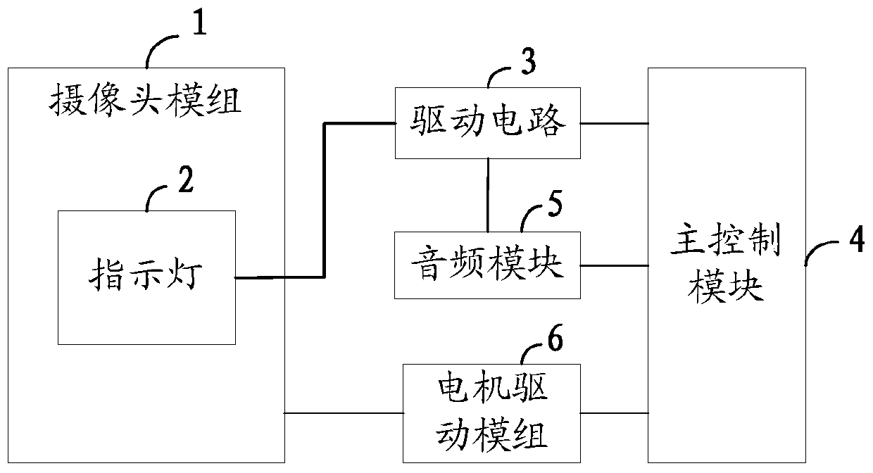
[0032] Such as figure 1 As shown, the embodiment of the present invention provides a terminal, including:

[0033] a housing, the housing is provided with a through hole;

[0034] A camera module 1, the camera module 1 extends out of the housing through the through hole or retracts into the housing;

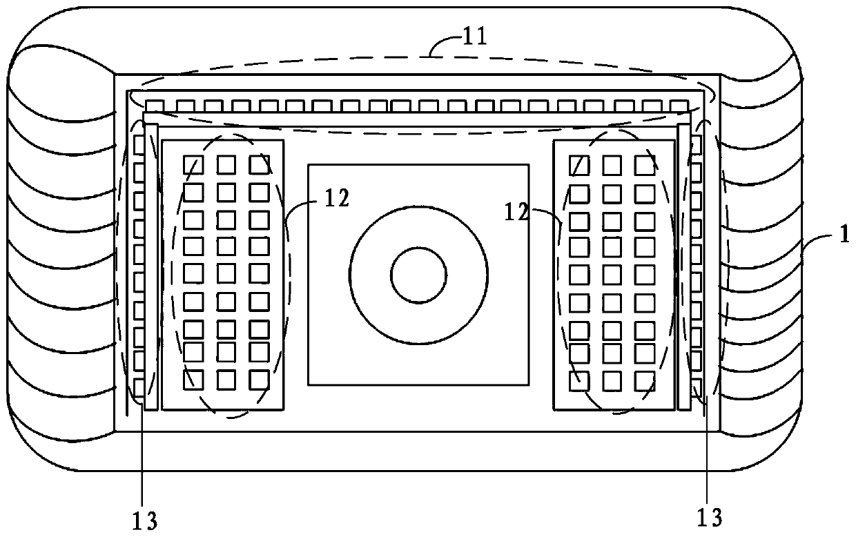
[0035] At least one indicator light 2 arranged in the camera module 1, when the number of the indicator lights 2 is more than two, the indicator lights...


PUM


Abstract

The invention provides a terminal and a camera lamp effect control method, and relates to the technical field of communication. The terminal comprises: a housing, which is provided with a through hole; a camera module extending out of the housing through the through hole or retracting into the housing; at least one indicator light arranged in the camera module, wherein when the number of the indicator lights is more than two, the indicator lights are arranged in a dot matrix form; the driving circuit is connected with the indicating lamp; and a main control module connected with the driving circuit. Based on the embodiments of the present invention, indicating lamps arranged in a dot matrix mode are additionally arranged in the camera module, the indicator lamp is controlled to generate different lighting effects according to different use scenes of the camera module; according to the technical scheme, the current state of the camera module or the terminal can be determined by a user according to the lighting effect, the light supplementing effect can be achieved on the photographing function of the camera when the indicator lamp is lightened, the user can feel the sense of science and technology when using the terminal, and the user experience is improved.

Description

technical field [0001] The present invention relates to the field of communication technologies, in particular to a method for controlling lighting effects of a terminal and a camera. Background technique [0002] With the rapid development of semiconductor technology, smart terminals have entered a new era, and full screens are becoming more and more popular with users. On this basis, lifting and rotating cameras have emerged as the times require. While enjoying the benefits of full screens, users can You can also have the ultimate camera experience, such as rotation tracking shooting and video recording, which enriches the life of users. Smart terminals with telescopic and rotating functions can greatly enhance user comfort and enrich users' lives, but there are also some shortcomings. For example, when the telescopic and rotating camera module is extended out of the terminal to work, often only the camera is working. Moreover, the entire camera module is relatively large...

Claims


Application Information

Patent Timeline
IPC IPC(8): H04N5/232H04N5/235
CPCH04N23/60H04N23/74
Inventor 郭超
Owner VIVO MOBILE COMM HANGZHOU CO LTD
Learn More