
Inner hole expansion grabbing mechanism

A grasping mechanism and a technology of expansion and tightening, which is applied in the field of inner hole expansion and tightening grasping mechanism, can solve problems such as difficulties, complex operating environment, not large enough, and can only effectively grasp single-layer workpieces, etc., to achieve shrinkage and dimensional stability , Small and compact space, strong mechanism rigidity

Pending Publication Date: 2019-08-09
四川成焊宝玛焊接装备工程有限公司
View PDF0 Cites 7 Cited by
  • Summary
  • Abstract
  • Description
  • Claims
  • Application Information

AI Technical Summary

Problems solved by technology

The operating environment of the automatic island of the workpiece cleaning robot is relatively complicated, and the gripping mechanism is required to be able to transfer the workpiece between different forms of positioning tooling. Both types of grippers can grab a single workpiece through the inner hole, but they must adapt to the workpiece cleaning robot. The complex operating environment of the automatic island is still very difficult; at the same time, the existing two-claw or three-claw mechanism can only effectively grab a single-layer workpiece due to the insufficient expansion force of the mechanism for workpieces with large inner holes. If two or more layers of workpieces are taken, the continuous compression state of the upper layer of workpieces cannot be effectively guaranteed, resulting in the free rotation of the upper layer of workpieces, the directional handling of the robot cannot be completed, and the various positioning tools of the automatic island cannot be adapted.

Method used


Image

  • Inner hole expansion grabbing mechanism
  • Inner hole expansion grabbing mechanism
  • Inner hole expansion grabbing mechanism

Examples


Embodiment Construction

[0032] Specific embodiments of the present disclosure will be described in detail below in conjunction with the accompanying drawings. It should be understood that the specific embodiments described here are only used to illustrate and explain the present disclosure, and are not intended to limit the present disclosure.

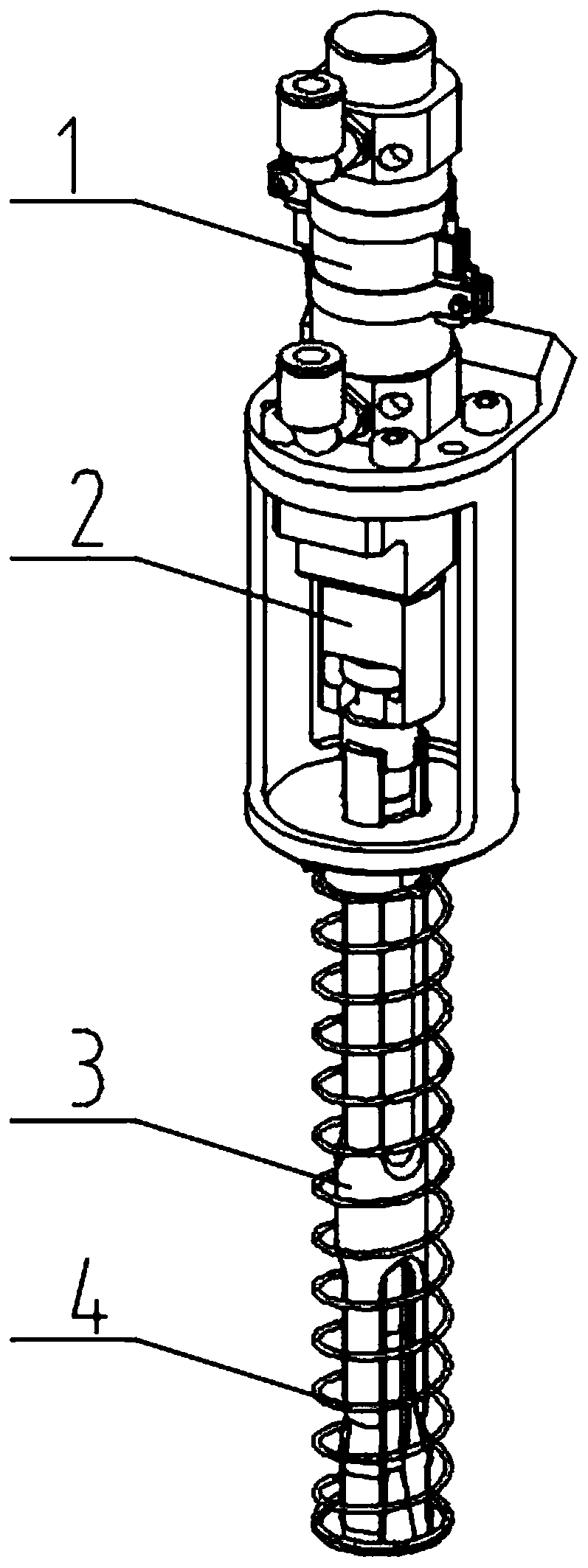
[0033] In this disclosure, unless stated otherwise, the used orientation words such as "up, down" are generally defined based on the orientation or positional relationship shown in the drawings, specifically refer to figure 1 The directions shown in the drawings are combined with the positional relationship of corresponding components in other drawings. When the following description refers to the accompanying drawings, the same numerals in different drawings refer to the same or similar elements unless otherwise indicated.

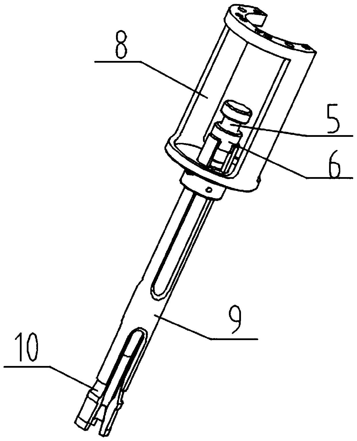
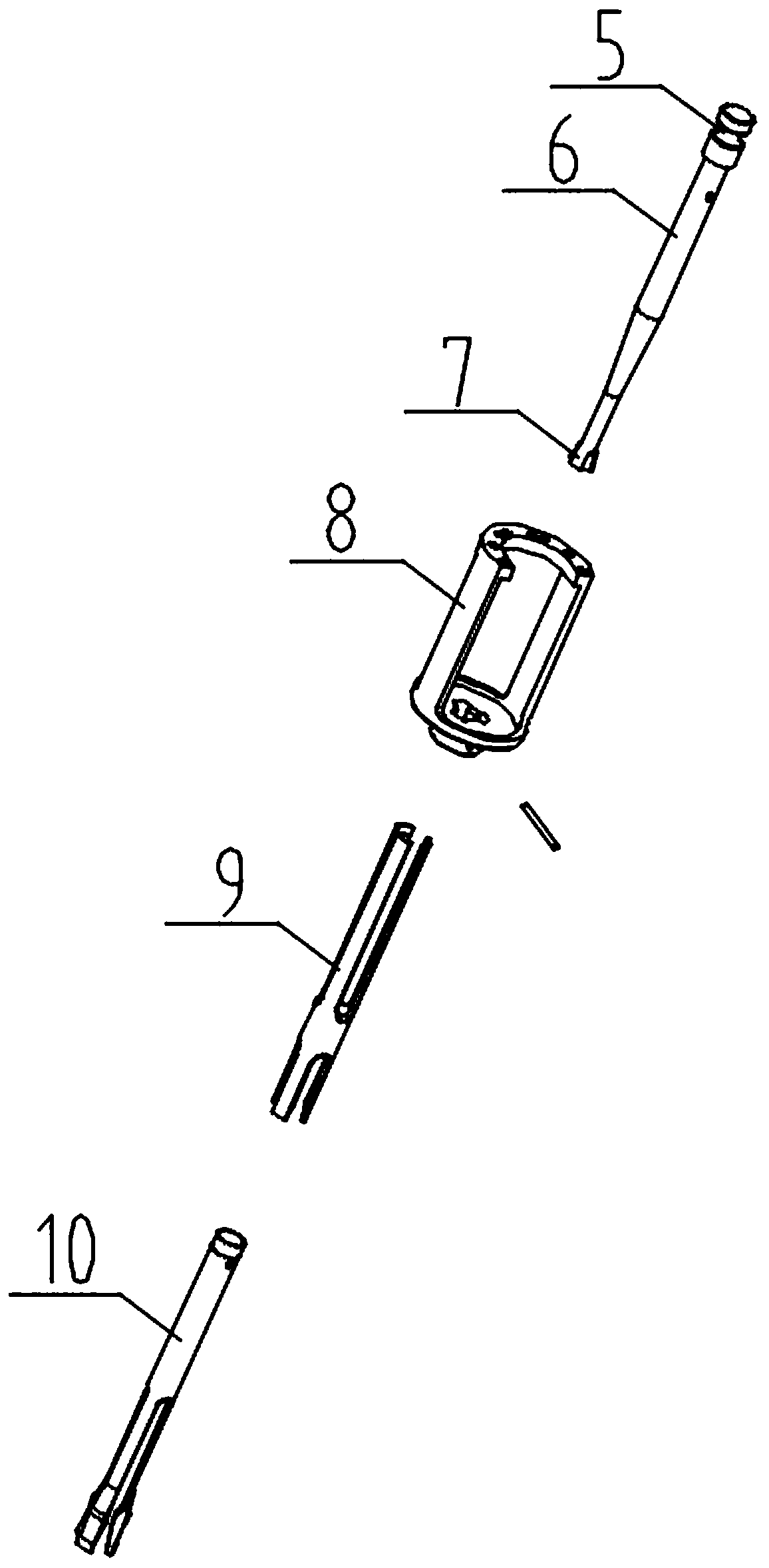
[0034] Such as figure 1 As shown, the present invention relates to an inner hole expansion and tightening grabbing mechanism, which i...


PUM


Abstract

The invention discloses an inner hole expansion grabbing mechanism, which comprises a pull rod, an expansion sleeve, a tightening sleeve and a power part. The expansion sleeve sleeves the outer side of the pull rod, and the tightening sleeve sleeves the outer side of the expansion sleeve; a hole-series workpiece sleeves the outer side of the expansion sleeve, and the pull rod, the expansion sleeveand the tightening sleeve are coaxially arranged; the pull rod and the expansion sleeve are fixed and can relatively move, the tightening sleeve and the pull rod are fixed, and the power part and thepull rod are connected; and the pull rod moves in the central axis direction of the pull rod, in the vertical moving process of the pull rod, the expansion sleeve expands outwards and contracts inwards, and when contracting inwards, the expansion sleeve is extruded by the tightening sleeve. An inner core coaxial sleeve structure, a middle expansion coaxial sleeve structure and an outer tighteningcoaxial sleeve structure are arranged, the space is small and compact, the mechanism is high in rigidity, high in bearing capacity and high in tightening capacity, particularly through the tighteningsleeve with the outer tightening function, the contraction state and size of the mechanism are stable, and a robot is quickly and accurately inserted into an inner hole of the workpiece advantageously to grab the workpiece.

Description

technical field [0001] The invention relates to the technical field of automobile manufacturing, in particular to an inner hole expansion and gripping mechanism. Background technique [0002] As an important part of the robot gripper, the grabbing mechanism applied to the automatic island of the workpiece cleaning robot is used to grab small automotive engine workpieces. However, the various workpieces included in the automotive engine small workpieces have inconsistent shapes and different sizes of inner holes. , the thickness varies, and the number of stacks varies. Due to the large difference in the shape of the workpiece to be grasped, the method of grasping the inner hole is adopted. [0003] At present, there are mainly two types of grasping mechanisms: one is a pneumatic (or electric) two-claw, and the other is a pneumatic (or electric) three-claw. The operating environment of the automatic island of the workpiece cleaning robot is relatively complicated, and the gr...

Claims


Application Information

Patent Timeline
Patent Type & Authority Applications(China)
IPC IPC(8): B25J15/00B08B13/00
CPCB25J15/00B08B13/00B25J15/0047
Inventor 王震寰李诚刘君陈季兰
Owner 四川成焊宝玛焊接装备工程有限公司
Learn More