
Coating equipment monitoring system and control method for coating equipment

A monitoring system and control method technology, which is applied to the surface coating liquid device, coating, measuring device, etc., can solve the problems of long working time and low working efficiency in the whole glue coating process

Active Publication Date: 2019-06-25
NIO ANHUI HLDG CO LTD
View PDF6 Cites 4 Cited by
  • Summary
  • Abstract
  • Description
  • Claims
  • Application Information

AI Technical Summary

Problems solved by technology

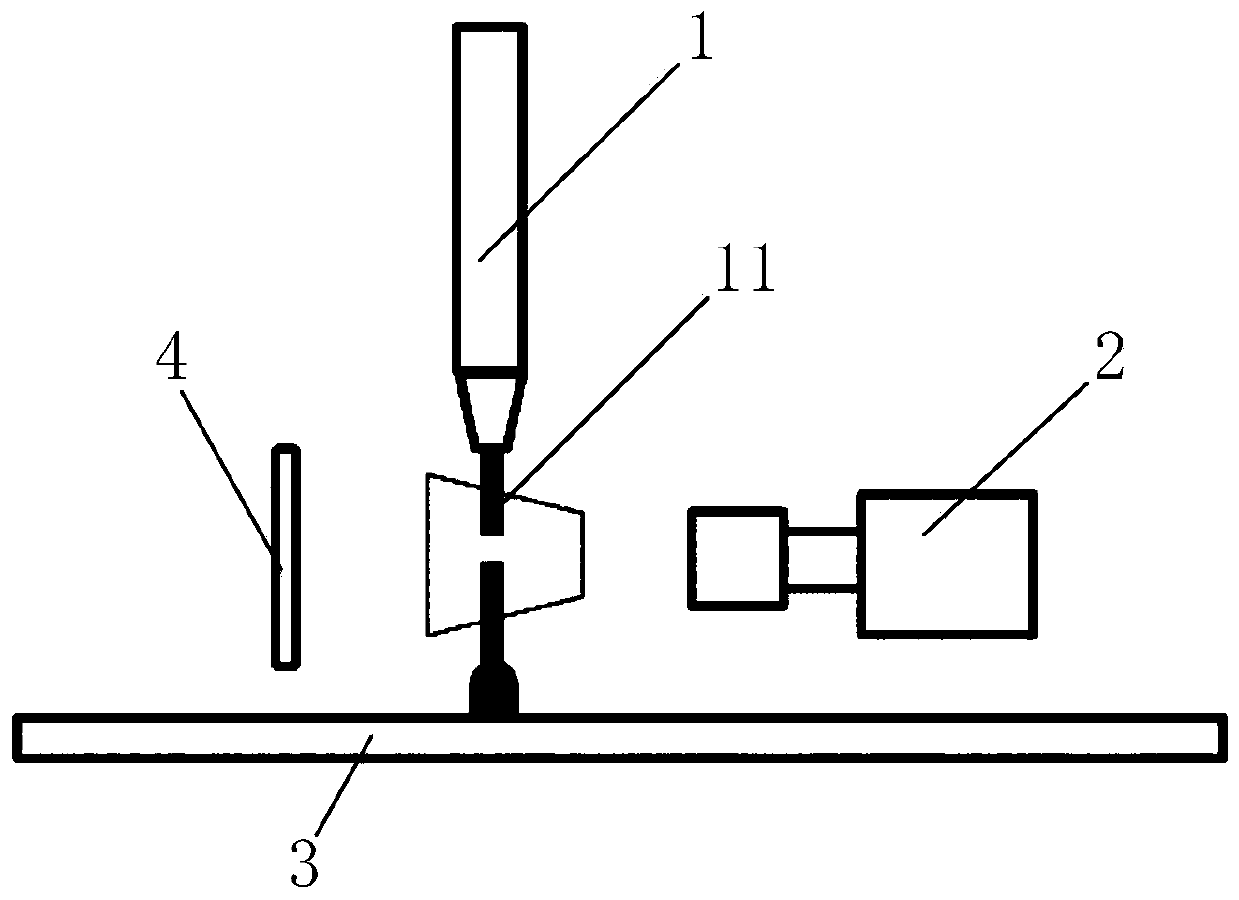
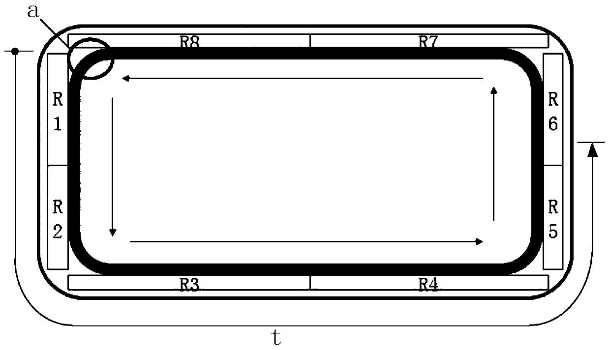
[0005] In order to solve the above-mentioned problems in the prior art, that is, in order to solve the problem that the existing gluing detection method prolongs the working time of the whole gluing process and the working efficiency is low, the present invention provides a monitoring system for gluing equipment, The gluing equipment includes a gluing device and a carrier, the monitoring system includes an image acquisition device, a control device and an alarm device, the carrier can carry parts to be glued, and the image acquisition device is arranged on the gluing device. On the device, the image acquisition device and the alarm device are connected in communication with the control device respectively, and the carrying device and the gluing device are relatively moved so that the gluing device moves along the The surface of the surface moves to apply glue, the image acquisition device can collect the glue output image of the glue application device, and the control device can judge whether the glue output image is abnormal and control the glue output when the glue output image is abnormal. alarm device alarm

Method used


Image

  • Coating equipment monitoring system and control method for coating equipment
  • Coating equipment monitoring system and control method for coating equipment
  • Coating equipment monitoring system and control method for coating equipment

Examples


Embodiment Construction

[0036] Those skilled in the art should understand that these embodiments are only used to explain the technical principles of the present invention, and are not intended to limit the protection scope of the present invention. Those skilled in the art can make adjustments as needed so as to adapt to specific applications.

[0037] It should be noted that, in the description of the present invention, terms such as "up", "down", "left", "right", and "vertical" indicate directions or positional relationships are based on the directions shown in the drawings Or positional relationship, which is only for convenience of description, and does not indicate or imply that the device or element must have a specific orientation, be constructed and operated in a specific orientation, and thus should not be construed as limiting the present invention.

[0038] In addition, it should be noted that, in the description of the present invention, unless otherwise clearly stipulated and limited, t...


PUM


Abstract

The invention belongs to the technical field of coating equipment, particularly provides a coating equipment monitoring system and a control method for coating equipment, and aims at solving the problems of the extending of the operation time of a whole coating working procedure by an existing coating detecting method and low operation efficiency. The system comprises an image collecting device, acontrol device and an alarming device which are arranged on the coating device, wherein the image collecting device can collect glue discharging images of the coating device, whether or not there exists abnormality in the glue discharging images can be judged by the control device, and the alarming device can be controlled to send an alarm when there exists abnormality in the glue discharging images. By means of device, the glue discharging state of the coating equipment can be monitored in real time by the monitoring system, a glue abnormal position can be discovered in the coating process,coating checking steps do not need to be conducted after coating, and the whole operation efficiency of the coating working procedure is improved.

Description

technical field [0001] The invention belongs to the technical field of gluing equipment, and in particular relates to a monitoring system for gluing equipment and a control method for gluing equipment. Background technique [0002] When the gluing equipment is gluing, because the glue supply device of the gluing equipment may be blocked or stagnant, the glue may be broken or the amount of glue is too much when the gluing equipment is sprayed out, resulting in waiting The glue is broken or the glue overflows in some parts of the glued parts. Not only will it affect the appearance flatness of the parts to be glued, but it may also reduce the sealing performance of the parts to be glued. [0003] The existing gluing detection method is as follows: after gluing is finished, inspection equipment is used to patrol and inspect the parts to be glued, so as to determine whether there is an abnormal position of glue coating on the parts to be glued. The disadvantage of this detectio...

Claims


Application Information

Patent Timeline
IPC IPC(8): B05C11/10G01N21/84
Inventor 吴页欣
Owner NIO ANHUI HLDG CO LTD
Learn More