Stator of rotating electric machine

A technology for rotating electrical machines and stators, which is applied in the direction of electromechanical devices, electrical components, electric components, etc., which can solve the problem of characteristic degradation and achieve the effect of suppressing the degradation of NV characteristics

Active Publication Date: 2019-05-21
HONDA MOTOR CO LTD
View PDF8 Cites 4 Cited by
  • Summary
  • Abstract
  • Description
  • Claims
  • Application Information

AI Technical Summary

Problems solved by technology

[0005] However, if an adhesive layer is provided on the entire area surrounding the coil in the slot as in the stator of a conventional rotating electrical machine, the coil, insulating paper, and stator core can be reliably integrated, but there is a problem due to rigidity of the stator. The problem that the NV (Noise Vibration: Noise Vibration) characteristic of the rotating electrical machine degrades due to high

Method used


Image

  • Stator of rotating electric machine
  • Stator of rotating electric machine
  • Stator of rotating electric machine

Examples


Embodiment Construction

[0036] Hereinafter, an embodiment of the present invention will be described with reference to the drawings. It should be noted that the drawings are viewed along the direction of the reference signs.

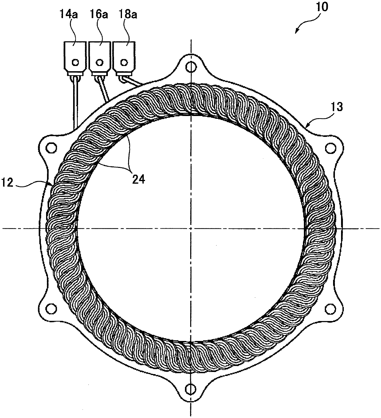
[0037] Rotating electrical machines are, for example, three-phase AC brushless motors such as figure 1 As shown, there is an annular stator 10 . A rotor (not shown) is rotatably arranged inside the stator 10. In the rotating electric machine, based on electric power supplied from a storage battery (not shown) through the U-phase terminal 14a, the V-phase terminal 16a, and the W-phase terminal 18a, respectively, Drive the rotor to rotate.

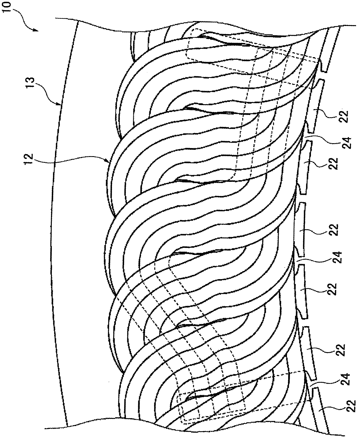
[0038] also refer to figure 2 , the stator 10 includes an annular stator core 13 and a coil 12 wound around the stator core 13 . The stator core 13 is provided with a plurality of teeth 22 protruding radially inward from an annular stator yoke and a plurality of slots 24 formed between adjacent teeth 22 . That is, a plurality of slots ...


PUM


Abstract

The present invention provides a stator of a rotating electric machine capable of improving NV characteristics while maintaining a structure in which a coil and a stator core are integrated via insulating paper. The stator (10) of the rotating electric machine includes a stator core (13) provided with a plurality of slots (24) along a circumferential direction, coils (12) of a plurality of phasesdistributedly wound around the stator core (13) via the plurality of slots (24), and an insulating paper disposed between the slot (24) and the coil (12). The insulating paper (27) has an adhesive portion which fixes the coil to the stator core and a part of the coil of each phase is fixed to the stator core (13) by the adhesive portion (28).

Description

technical field [0001] The invention relates to a stator for a rotating electrical machine. Background technique [0002] Such as Figure 8 As shown, the stator of the rotating electrical machine has a stator core 31 and a coil 32 . The stator core 31 has a plurality of teeth 33 protruding inward in the radial direction (arrow A direction) and arranged in the circumferential direction (arrow B direction), and slots 34 are formed between adjacent teeth 33 . The coil 32 is inserted into the slot 34, and the insulating paper 35 is attached between the coil 32 and the surface 34s forming the slot 34 so as to surround the coil 32 in the axial direction of the rotary electric machine. In addition, adhesive layers 36 are provided on both surfaces of the region surrounding the coil 32 of the insulating paper 35 (see Patent Document 1). The coil 32 and the insulating paper 35 are fixed by an adhesive layer 36 formed on one surface of the insulating paper 35, and the insulating pape...

Claims


Application Information

Patent Timeline
Patent Type & Authority Applications(China)
IPC IPC(8): H02K3/28H02K3/34
CPCH02K15/10H02K3/345H02K3/28H02K1/16
Inventor 山口直志加藤龙太郎甲田智弘川野裕介菅原顶志太田知介佐佐木忠道丸山泰佑
Owner HONDA MOTOR CO LTD
Why Eureka
Try Eureka