
Visible oral cavity spatula

An oral cavity and scraper technology, which is applied in the field of oral cleaning tools, can solve the problems of tooth soft tissue damage, oral cleaning instruments that are difficult to clean dental calculus pigmentation, and are easy to cause accidental injuries, so as to achieve the effect of solving dental calculus

Pending Publication Date: 2019-04-23
周星
View PDF8 Cites 2 Cited by
  • Summary
  • Abstract
  • Description
  • Claims
  • Application Information

AI Technical Summary

Problems solved by technology

[0005] The patient is at home, and it is difficult for the patient to clean the dental calculus, dental plaque, pigmentation, etc.
However, when the commonly used tongue coating cleaners, various toothbrushes or flushers are used to clean the teeth and the back of the tongue, these cleaning operations are difficult to observe due to the dark light in the oral cavity, or the cleaning part is relatively hidden, and the patient can only do it by feeling. Operation, usually the parts to be cleaned cannot be cleaned, and the parts that do not need to be cleaned are repeatedly cleaned, causing excessive damage to the teeth or soft tissues in the oral cavity, especially when cleaning with high-speed rotating or vibrating tools, such as high-speed grinding heads, Ultrasonic grinding head, bur and other tools, when the patient cleans his own mouth, once the working head deviates from the working part, it is easy to cause accidental injury

Method used


Image

  • Visible oral cavity spatula
  • Visible oral cavity spatula
  • Visible oral cavity spatula

Examples


Embodiment 1

[0058] Embodiment 1: The visible oral spatula of the present invention

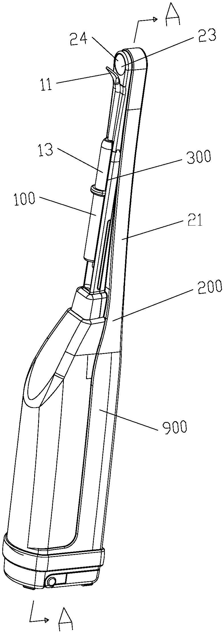
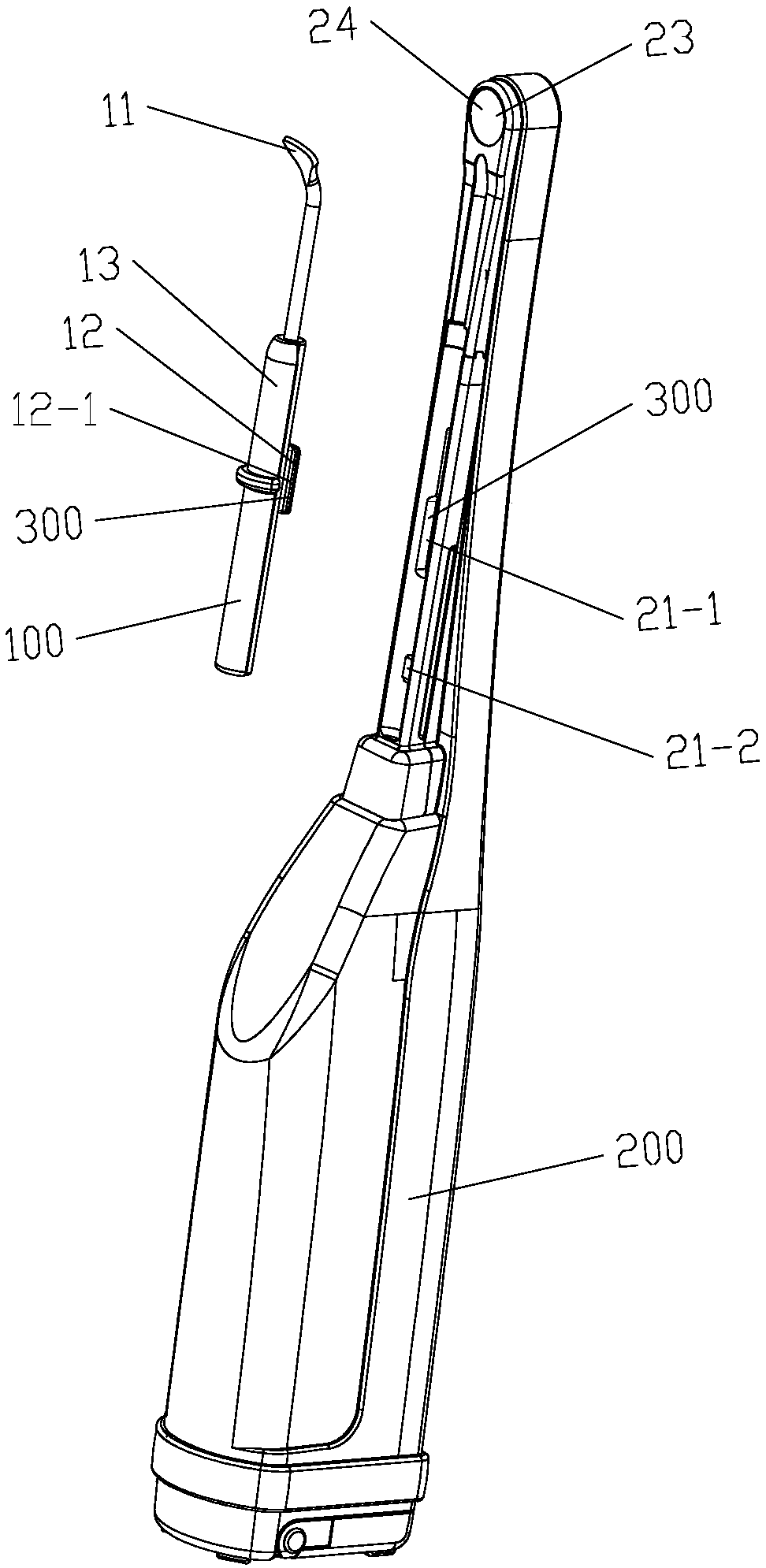
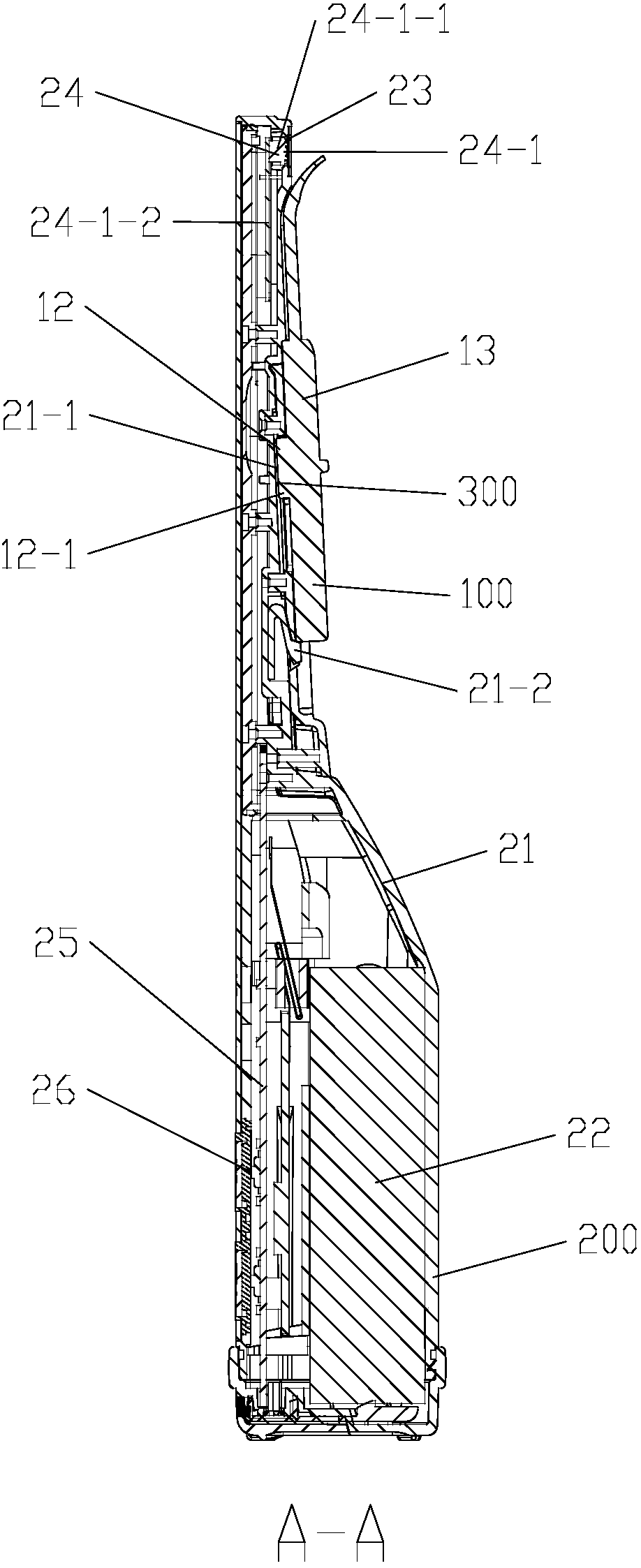
[0059] refer to Figure 1 to Figure 1-3 , the visible oral spatula 900 of this embodiment includes an oral spatula 100 , an oral viewer 200 and a connecting mechanism 300 .

[0060] refer to figure 1 and Picture 1-1 , the oral spatula 100 includes a scraper 11 , a loading and unloading mechanism 12 , and a bracket 13 . The scraper 11 is arranged at the front end of the bracket 13; it is used to install the oral spatula 100 on the oral viewer 200 or to disassemble the oral spatula 100 from the oral viewer 200 The loading and unloading mechanism 12 is located on the bracket 13 .

[0061] The oral viewer 200 includes a housing 21 , a power supply system 22 , a lighting system 23 , an observation system 24 , a circuit system 25 and a switch 26 . The lighting system 23, the observation system 24, the circuit system 25 and the power supply system 22 are installed in the housing 21, and the switch 26 is in...

Embodiment 2

[0078] Embodiment 2: Visible oral spatula with flusher of the present invention

[0079] refer to Figure 5 to Figure 5-2 The difference between this embodiment and Embodiment 1 is that, in this embodiment, the oral viewer 200 is further provided with a flusher 404 capable of flushing and cleaning the oral cavity.

[0080] refer to Figure 5-2 , the flusher 404 includes a nozzle 404-1, a water tank 404-2, a water pipe 404-3, a water spray switch 404-4 and a booster 404-5. The water tank 404-2 and the pressurizing device 404-5 are installed in the housing 21 of the oral viewer 200; the nozzle 404-1 is installed at the front end 200-1 of the oral viewer 200 The vicinity of System 24.


PUM


Abstract

The invention provides a visible oral cavity spatula. The visible oral cavity spatula comprises an oral cavity spatula body, an oral cavity observation instrument and a connecting mechanism. The oralcavity spatula body is detachably connected to the oral cavity observation instrument through the connecting mechanism, under the action of an observation system of the oral cavity observation instrument, teeth or a tongue body can be scraped and cleaned by using the oral cavity spatula body under direct vision, the cleaning effect is observed in real time, and the cleaning process can be shot andrecorded. The oral cavity observation instrument can be further provided with a flusher, when the flusher is matched with the oral cavity spatula body in use, dental calculus, dental plaque, tongue coat and other dirt which are cleaned away can be washed out in time, and the using process is more comfortable, more convenient and more efficient.

Description

technical field [0001] The invention relates to an oral cavity cleaning tool, in particular to a visible oral cavity scraper for cleaning teeth, interdental spaces and oral cavity. Background technique [0002] When the teeth are not cleaned for a long time, or if you smoke, drink tea, or drink alcohol for a long time, it is very easy to produce dental problems such as calculus, dental plaque, and pigmentation on the surface of the teeth, and it is also easy to cause thickening of the tongue coating. At present, the conventional way to remove dental calculus, dental plaque, pigmentation, tongue coating, etc. is to wash teeth in a professional stomatological hospital. [0003] At present, in the process of cleaning teeth in hospitals or dental clinics, the commonly used method of removing dental calculus, dental plaque, and pigmentation is to extend the working head of the dental cleaner through high-speed rotation or vibration into the oral cavity, and the friction or vibrat...

Claims


Application Information

Patent Timeline
Patent Type & Authority Applications(China)
IPC IPC(8): A61B17/24A61C17/00A61C17/02A61B1/24A61B1/04A61B1/06
CPCA61B1/04A61B1/06A61B1/24A61B17/244A61C17/00A61C17/02A61B1/247A61B1/00087A61B1/00101A61B1/0014A61B1/00016A61B1/00032A61B1/00045A61B1/00105A61B1/05A61B1/0676A61C17/0202A61B1/00009
Inventor 周星苏文宇徐华苹周玮
Owner 周星
Learn More