
Data interface device and chute

A data interface and chute technology, applied in the field of data transmission, can solve problems such as high cost, inability to meet large-scale, irregular data transmission requirements, low efficiency, etc., achieve low manufacturing cost, promote large-scale application, and save time Effect

Active Publication Date: 2020-11-24
JD DIGITS HAIYI INFORMATION TECHNOLOGY CO LTD
View PDF6 Cites 0 Cited by
  • Summary
  • Abstract
  • Description
  • Claims
  • Application Information

AI Technical Summary

Problems solved by technology

However, manual plugging and high-precision robotic arm plugging are too costly and inefficient to meet large-scale and irregular data transmission needs.

Method used


Image

  • Data interface device and chute
  • Data interface device and chute
  • Data interface device and chute

Examples


Embodiment Construction

[0039] The present invention is described below based on examples, but the present invention is not limited to these examples. In the following detailed description of the invention, some specific details are set forth in detail. The present invention can be fully understood by those skilled in the art without the description of these detailed parts. In order to avoid obscuring the essence of the present invention, well-known methods, procedures, and flow charts are not described in detail. Additionally, the drawings are not necessarily drawn to scale.

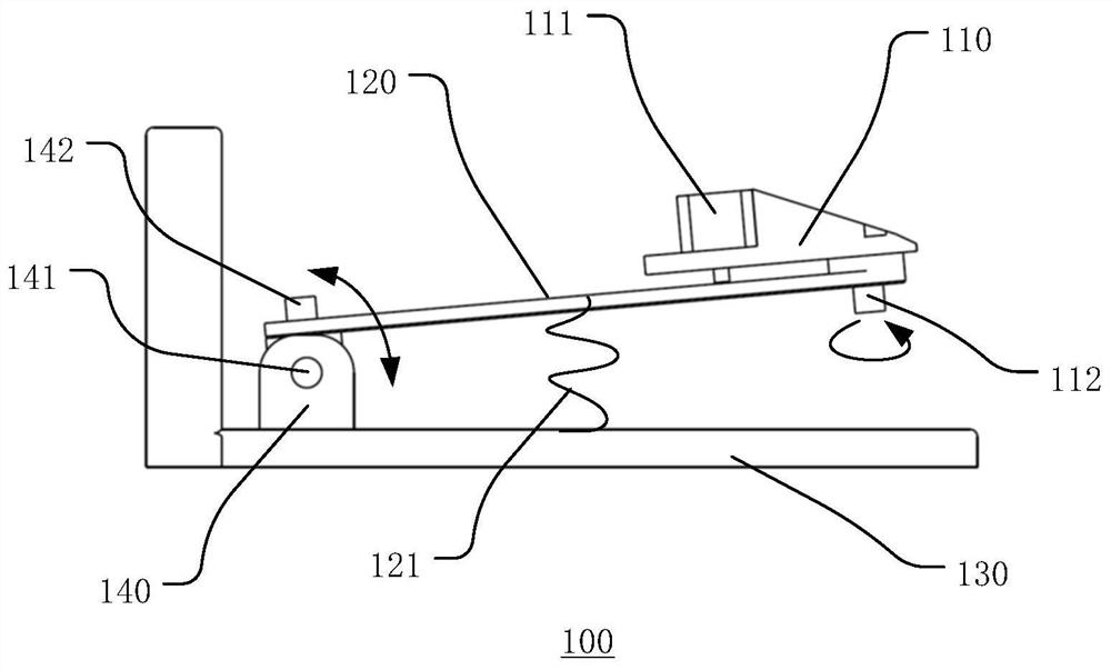
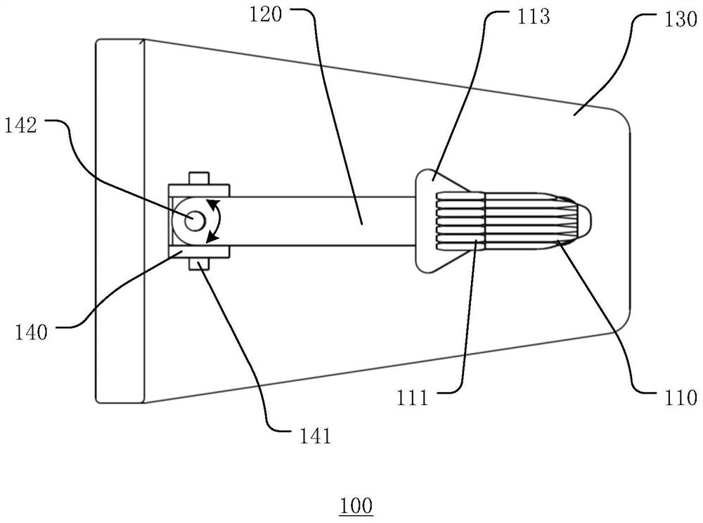
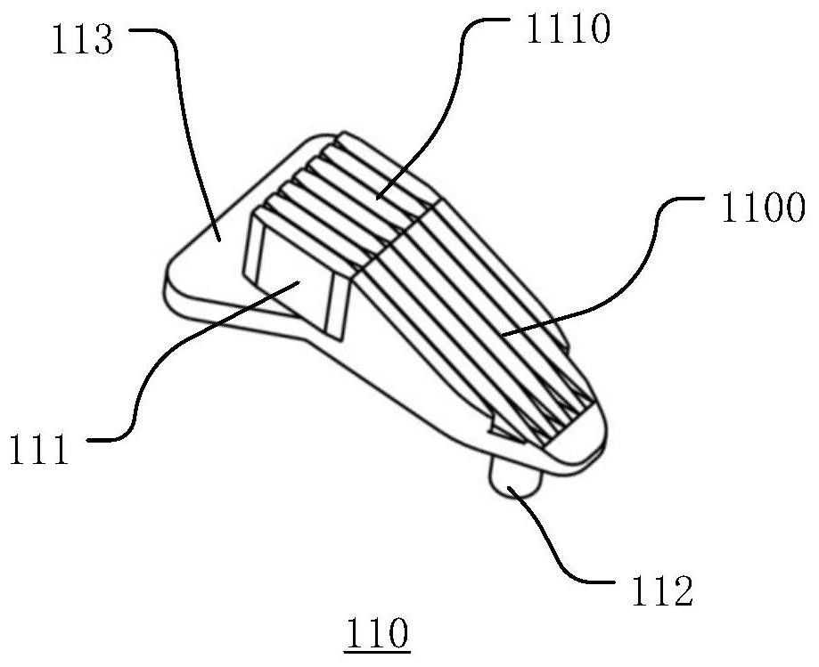
[0040] Figure 1a and Figure 1b A side view and a top view of the data interface device according to the embodiment of the present invention are respectively shown. In the figure, the data interface device 100 includes a guide device 110 , a connecting rod 120 , a base 130 and a support 140 . Wherein, the guide device 110 includes a connecting piece 111 and a connecting column 112 , and data transmission between the two is...


PUM


Abstract

A data interface device (100) and sliding groove (200), the data interface device (100) comprising a guide device (110) and a connector (111) located on the guide device (110). The guide device (110) guides the connector (111) in the horizontal direction and the vertical direction to realize the connection of the connector (111), thereby enabling the data interface device (100) to be quickly inserted and removed. The data interface sliding groove (200) comprises: a main body (210), comprising an inlet end (211), a connecting end (212), and a slideway (213) located between the inlet end (211) and the connecting end (212); and a contact piece (220) located at the connecting end (212) of the main body (210) for connecting. The size of the slideway (213) gradually decreases from the inlet end (211) to the connecting end (212), and the connector (111) of the data interface device (100) entering the slideway (213) is gradually guided to the contact piece (220). A tolerance mechanism formed by the guide device (110) cooperating with the slideway (213) is used to perform error compensation on the spatial positions where the data interface device (100) and the data interface sliding groove (200) are located, achieving the connection of the data interface by means of automatic guidance.

Description

technical field [0001] The invention relates to the technical field of data transmission, in particular to a data interface device and a chute that can be quickly inserted and removed by a mobile robot. Background technique [0002] At present, in some confidential environments such as financial computer rooms and data computer rooms, wireless data transmission is prohibited due to data confidentiality requirements, but such confidential environments also have data transmission requirements, and manual methods are usually used at this stage To achieve, artificially realizing data transmission in a confidential environment can only meet a small number of individual data transmission requirements, and it is unrealistic to manually realize large-area, large-volume, and irregular data transmission requirements. With the development of science and technology, the application range of mobile robots is becoming wider and wider, such as inspection, handling, security, etc. Some robo...

Claims


Application Information

Patent Timeline
Patent Type & Authority Patents(China)
IPC IPC(8): H01R13/629H01R24/00
CPCH01R13/629H01R24/00
Inventor 秦宇姚秀军
Owner JD DIGITS HAIYI INFORMATION TECHNOLOGY CO LTD
Learn More