Roof intelligent signal flight platform

A flight platform and signal technology, applied in aircraft, motor vehicles, aircraft parts, etc., can solve problems such as inability to detect traffic lights and the surrounding traffic environment, unfavorable to detect the traffic environment around the device, and limit performance, etc., to achieve a wide range of applications. , Easy to install and use, flexible control effect

Inactive Publication Date: 2019-03-01
钟志刚
View PDF0 Cites 2 Cited by
  • Summary
  • Abstract
  • Description
  • Claims
  • Application Information

AI Technical Summary

Problems solved by technology

[0002] The rapid development and popularization of vehicle intelligent control, automatic driving, and assisted driving. Using various signal detection transceiver devices to detect the vehicle itself and the surrounding traffic environment is the key guarantee for the performance of various intelligent control, automatic driving, and assisted driving systems. Since the height of the vehicle itself limits the installation height of the detection equipment, the surrounding traffic facilities, other vehicles, and the vehicle itself will form a blind area for the detection equipment, which is not conducive to the detection equipment's complete grasp of the traffic environment around the vehicle and limits the intelligent control system of the vehicle. Performance, especially for small cars with a low body, it is easy to be blocked by surrounding guardrails, green belts, traffic isolation belts, and other taller vehicles, and it often happens that traffic lights and the surrounding traffic environment cannot be detected

Method used


Image

  • Roof intelligent signal flight platform
  • Roof intelligent signal flight platform

Examples


Embodiment Construction

[0018] In order to make the technical means, features, goals and effects achieved by the present invention easy to understand, the present invention will be further elaborated below in combination with a diagram of an embodiment.

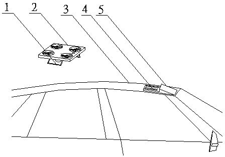
[0019] Such as figure 1 As shown, the roof intelligent signal flight platform is installed on the top of the vehicle, and the flight platform body 2 flies or hovers above the vehicle 3 or at any position in the low altitude around it. The vehicle recovery structure 5 is connected and fixed on the top of the vehicle roof. The flight platform body 2 and The vehicle-mounted recovery structure 5 is equipped with fixed docking and releasing devices 1 and 4 respectively, and the vehicle-mounted recovery structure 5 can be fixedly installed on different vehicles 3 in cooperation with the vehicle structure.

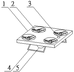
[0020] Such as figure 2 As shown, the roof intelligent signal flying platform includes the following parts: a flying platform body 1, a flying rotor...


PUM


Abstract

The invention relates to a roof intelligent signal flight platform. The roof intelligent signal flight platform comprises a flight platform body and a vehicle-mounted recovery structure, wherein the flight platform body is a signal detecting, receiving and sending device for intelligent control of various vehicles and provides a detecting, receiving and sending position for flying at a low altitude on a roof; the flight platform body flies by adopting an unmanned aerial vehicle technology, is stored and charged by a vehicle-mounted recovery structure fixed on the roof, and realizes release, docking and fixation of take-off and landing; the vehicle-mounted recovery structure can be fixedly mounted on various vehicles or means of transportation; and detection, control and navigation data signals between the flight platform body and the vehicle-mounted recovery structure and between between the flight platform body and vehicle-mounted equipment are wirelessly transmitted. The invention provides a higher detection position for a vehicle intelligent control signal detecting, receiving and sending device, expands the range of vehicle signal detecting, receiving and sending, and effectively improves the intelligent control performance of a vehicle; the roof intelligent signal flight platform has flexible detection position control, is convenient to mount and apply, is suitable for various vehicles, and has a very wide application range in the fields of intelligent control, automatic driving and auxiliary driving of vehicles.

Description

technical field [0001] The invention relates to a vehicle-mounted signal platform, in particular to an intelligent signal flight platform on the vehicle roof. Background technique [0002] The rapid development and popularization of vehicle intelligent control, automatic driving, and assisted driving. Using various signal detection transceiver devices to detect the vehicle itself and the surrounding traffic environment is the key guarantee for the performance of various intelligent control, automatic driving, and assisted driving systems. Since the height of the vehicle itself limits the installation height of the detection equipment, the surrounding traffic facilities, other vehicles, and the vehicle itself will form a blind area for the detection equipment, which is not conducive to the detection equipment's complete grasp of the traffic environment around the vehicle and limits the intelligent control system of the vehicle. Performance, especially for small cars with a lo...

Claims


Application Information

Patent Timeline
Patent Type & Authority Applications(China)
IPC IPC(8): B64C39/02B64F1/00G08G1/0967
CPCB64C39/02B64F1/00G08G1/096708G08G1/096766
Inventor 钟志刚
Owner 钟志刚
Why Eureka
Try Eureka