A discharge guide device for automatic feeding and discharging of transformer rubber encapsulation machine
A technology of a diversion device and a rubber encapsulation machine, which is used in the manufacture of inductors/transformers/magnets, packaging/impregnation, electrical components, etc. Effect
- Summary
- Abstract
- Description
- Claims
- Application Information
AI Technical Summary
Problems solved by technology
Method used
Image


Examples
Embodiment 1
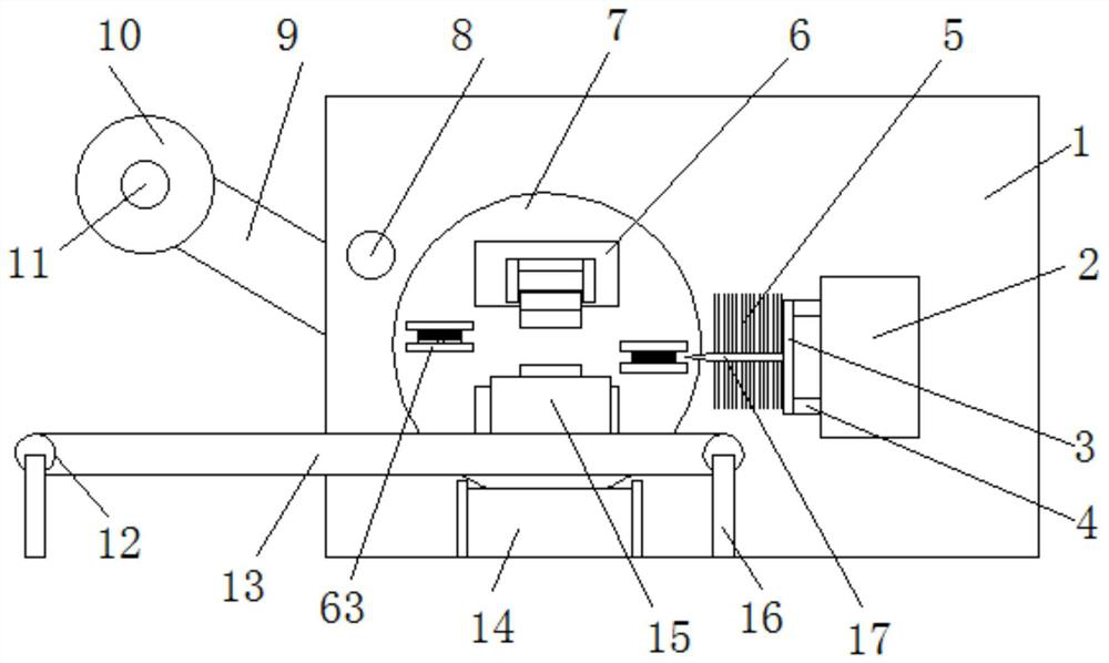
[0041] Example 1, please refer to Figure 1-4 , A discharging diversion device for automatic feeding and discharging of a transformer encapsulating machine, comprising a encapsulating machine main body 1, a turntable 7, a transformer 23, a encapsulating fixing base 41, and a material belt bracket 9. The encapsulating machine body 1 is provided with There is a turntable driving device 35, the turntable driving device 35 drives the turntable 7 to rotate through the main shaft 36, the main body 1 of the laminating machine is fixedly installed with a tape support 9 for mounting the tape, and there is a The fixed roller 11 is movably connected, the fixed roller 11 is provided with a uniformly wound material tape, and a feeding roller 8 fixed on the main body 1 of the rubber covering machine is arranged between the material tape support 9 and the rubber covering fixing base 41, The side of the turntable 7 is provided with a knife holder 3, one side of the knife holder 3 is provided wi...
Embodiment 2
[0045] The same points as Embodiment 1 will not be repeated, and the differences from Embodiment 1 are:
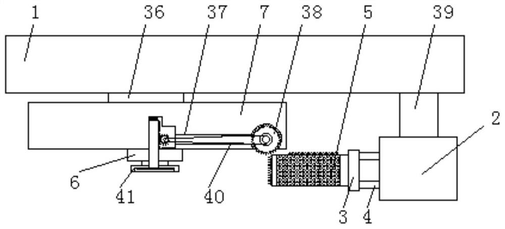
[0046] See Image 6 Preferably, the bottom of the rubber-coated fixing base 41 is provided with a downwardly inclined discharging chute 14, and both sides of the upper end of the discharging chute 14 are provided with a vertical downward and fixedly connected first fixing rod 56, One side of the middle of the first fixed rod 56 is provided with a second fixed rod 55 that is vertical and fixedly connected. The front end of the second fixed rod 55 is connected to the bottom of the discharge chute 14, and the other of the first fixed rod 56 is A number of vertical and fixedly connected third fixing rods 57 are arranged on the side, and the front end of the third fixing rods 57 is fixedly connected with the main body 1 of the rubber coating machine. The design of the discharging chute 14 can effectively divert the transformer 23 after the encapsulation is completed to the set pos...
Embodiment 3
[0048] The same points as the embodiment 1 will not be repeated, and the differences from the embodiment 1 are:
[0049] See figure 2 Preferably, the deflector 19 is shaped like a "eight", and the cross section at the outlet of the deflector 19 is the same size as the transformer 23.
[0050] Preferably, the cross section of the push plate 22 is the same size as the cross section of the feed slot 25 and the cross section of the transformer 23.
[0051] Preferably, the outer side of the conveyor belt 24 is provided with a symmetrically distributed fixed frame 13, the two ends of the conveyor belt 24 are provided with symmetrically distributed conveyor wheels 12, and the conveyor belt 24 is connected to the fixed frame 13 through the conveying wheels 12, and the fixed frame There are a number of fixed frames 16 evenly and symmetrically distributed at the bottom of 13.
PUM
 Abstract
Description
Claims
Application Information
 - R&D
- Intellectual Property
- Life Sciences
- Materials
- Tech Scout
- Unparalleled Data Quality
- Higher Quality Content
- 60% Fewer Hallucinations
Browse by: Latest US Patents, China's latest patents, Technical Efficacy Thesaurus, Application Domain, Technology Topic, Popular Technical Reports.
© 2025 PatSnap. All rights reserved.Legal|Privacy policy|Modern Slavery Act Transparency Statement|Sitemap|About US| Contact US: help@patsnap.com