
Welding-free strip light port power supply connector and welding-free strip light power supply connection method

A technology of power connectors and light strips, which is applied in the direction of connection and connection of parts and circuits of devices, can solve problems such as safety risks, line failures, poor construction quality, etc., and achieve the effect of simplifying operating procedures and improving efficiency

Pending Publication Date: 2019-02-01
SHEN ZHEN TOP LINK TECH CO LTD +1
View PDF3 Cites 1 Cited by
  • Summary
  • Abstract
  • Description
  • Claims
  • Application Information

AI Technical Summary

Problems solved by technology

However, this connection method requires the use of special welding equipment to complete the connection work; since the installation environment of LED light strips is often in complex working conditions that are difficult to reach such as high altitudes, walls, and ceilings, it is necessary to carry the welding equipment and pull the welding equipment Special power transmission cables are used to carry out operations, which seriously hinders the operation of itself and other stations, resulting in low construction efficiency and poor construction quality; at the same time, because the welding points are completely exposed to the air and are easy to oxidize, the line fails, and Being exposed for a long time can easily lead to security risks

Method used


Image

  • Welding-free strip light port power supply connector and welding-free strip light power supply connection method
  • Welding-free strip light port power supply connector and welding-free strip light power supply connection method
  • Welding-free strip light port power supply connector and welding-free strip light power supply connection method

Examples


Embodiment Construction

[0031] In order to describe the technical content and structural features of the present invention in detail, further description will be given below in conjunction with the implementation and accompanying drawings.

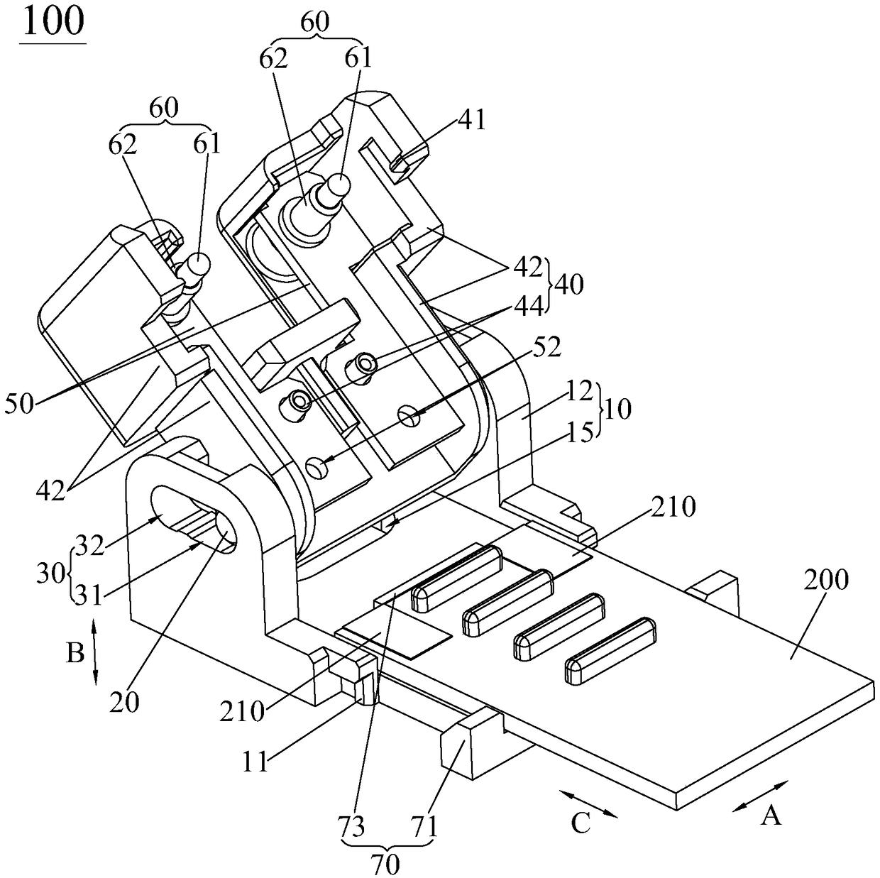
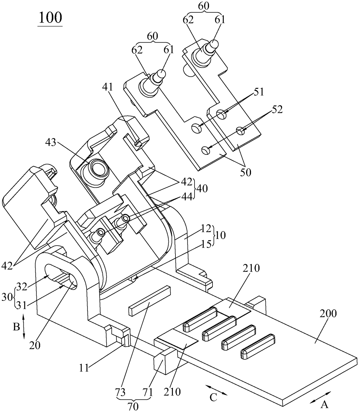
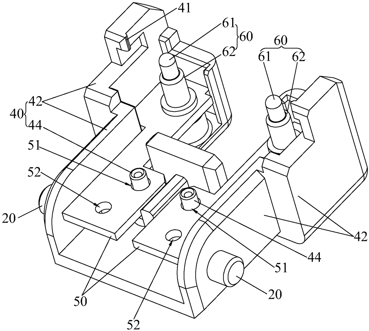
[0032] see figure 1 , Figure 6 and Figure 7 , the solderless light strip port power connector 100 of the present invention includes a base 10 for carrying the light strip 200 , a cover that turns over a mounting axis 20 relative to the base 10 and slides relative to the base 10 along a guide rail 30 40. The PCB board 50 installed on the cover 40 and the probe 50 pierced on the PCB 40. Preferably, the probe 40 is along the upper and lower sides of the seat 10 when the cover 40 is in the cover position described below. The direction is set at the PCB board 40, but not limited thereto. The installation shaft 20 is arranged along the left-right direction of the seat body 10 (i.e. the direction indicated by the double arrow A), so that the cover body 40 moves up ...


PUM


Abstract

The invention discloses a welding-free strip light port power supply connector which comprises a seat, a cover which overturns relative to the seat around an installation axis and slide along a guiderail, a PCB installed in the cover and probes arranged in the PCB. The cover includes at least a turn-out position, a covering position and a locking position relative to the seat, the cover is switched between the turn-out position and the covering position, the cover in the covering position slide along the guide rail and is thus switched between the covering position and the locking position, one of the cover and the seat includes a locking portion, the other of the same includes a matched locking portion, and when the cover is changed from the turn-over position to the covering position, shafts of the probes abut against a strip light on the seat along the vertical direction of the seat, the cover slides to the locking position along the guide rail, and thus, the locking portion slidesto the position where the locking portion can be locked with the matched locking portion, and the probe shafts slides to position where the shafts can electrically presses a port of the strip light.Thus, it is not required to weld the strip light to a power line, work is simplified, and the efficiency is improved. The invention also discloses a welding-free strip light power supply connection method.

Description

technical field [0001] The present invention relates to a power supply connector, in particular to a solder-free type light strip port power connector and a welding-free method for connecting a light strip power supply to realize welding-free operation of a light strip and a power cord. Background technique [0002] With the continuous development of the economy and the continuous progress of the society, various material consumer goods are provided for people's lives, and light strips, especially LED light strips, are one of many material consumer goods. [0003] At present, in the existing power access connection scheme of the LED light strip, the positive and negative poles of the power cord are welded to the two pads of the LED light strip port respectively, so as to realize the connection of the power supply to the LED light strip. However, this connection method requires the use of special welding equipment to complete the connection work; since the installation enviro...

Claims


Application Information

Patent Timeline
Patent Type & Authority Applications(China)
IPC IPC(8): H01R13/40H01R13/502H01R13/627H01R13/629H01R43/20
CPCH01R13/40H01R13/502H01R13/627H01R13/629H01R43/20
Inventor 徐炎马增世石进宝
Owner SHEN ZHEN TOP LINK TECH CO LTD
Learn More