
A waterproof cover and a waterproof assembly for a JP cabinet

A waterproof cover and component technology, applied in the field of transformers, can solve the problems of limited ventilation, water leakage, affecting the temperature rise of JP cabinets, etc., and achieve the effect of facilitating later maintenance and improving production efficiency

Inactive Publication Date: 2019-01-15
QINGDAO TGOOD ELECTRIC
View PDF10 Cites 4 Cited by
  • Summary
  • Abstract
  • Description
  • Claims
  • Application Information

AI Technical Summary

Problems solved by technology

In order to meet this requirement, ventilation louvers are generally installed on the side wall of the JP cabinet. The traditional scheme of spot-welding stainless steel mesh inside the louvers has sufficient ventilation, but there is a risk of water leakage in the 180° water spray test. Some companies install additional louvers outside the cabinet. The cover plate can avoid the 180° water spray test and meet the waterproof requirements, but the ventilation volume will be greatly restricted, which will affect the temperature rise of the JP cabinet.

Method used


Image

  • A waterproof cover and a waterproof assembly for a JP cabinet
  • A waterproof cover and a waterproof assembly for a JP cabinet
  • A waterproof cover and a waterproof assembly for a JP cabinet

Examples


Embodiment 1

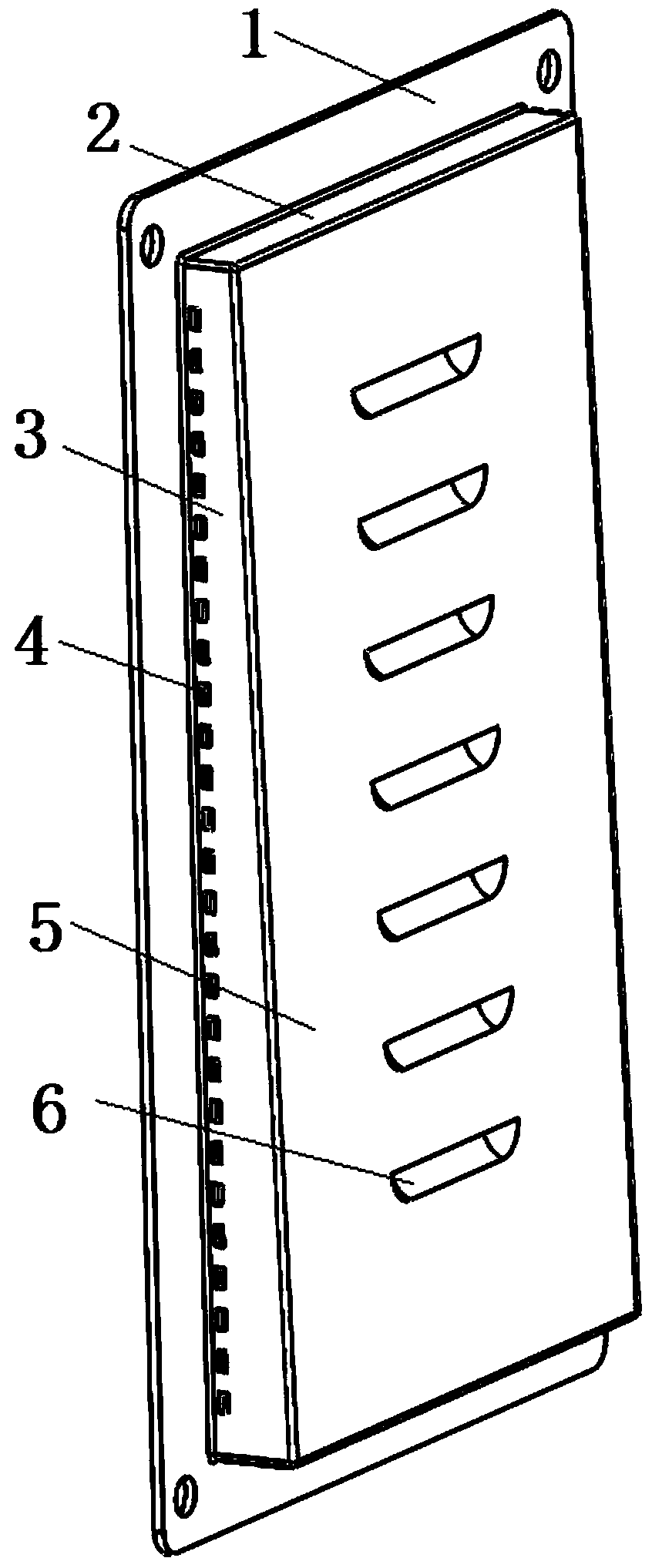
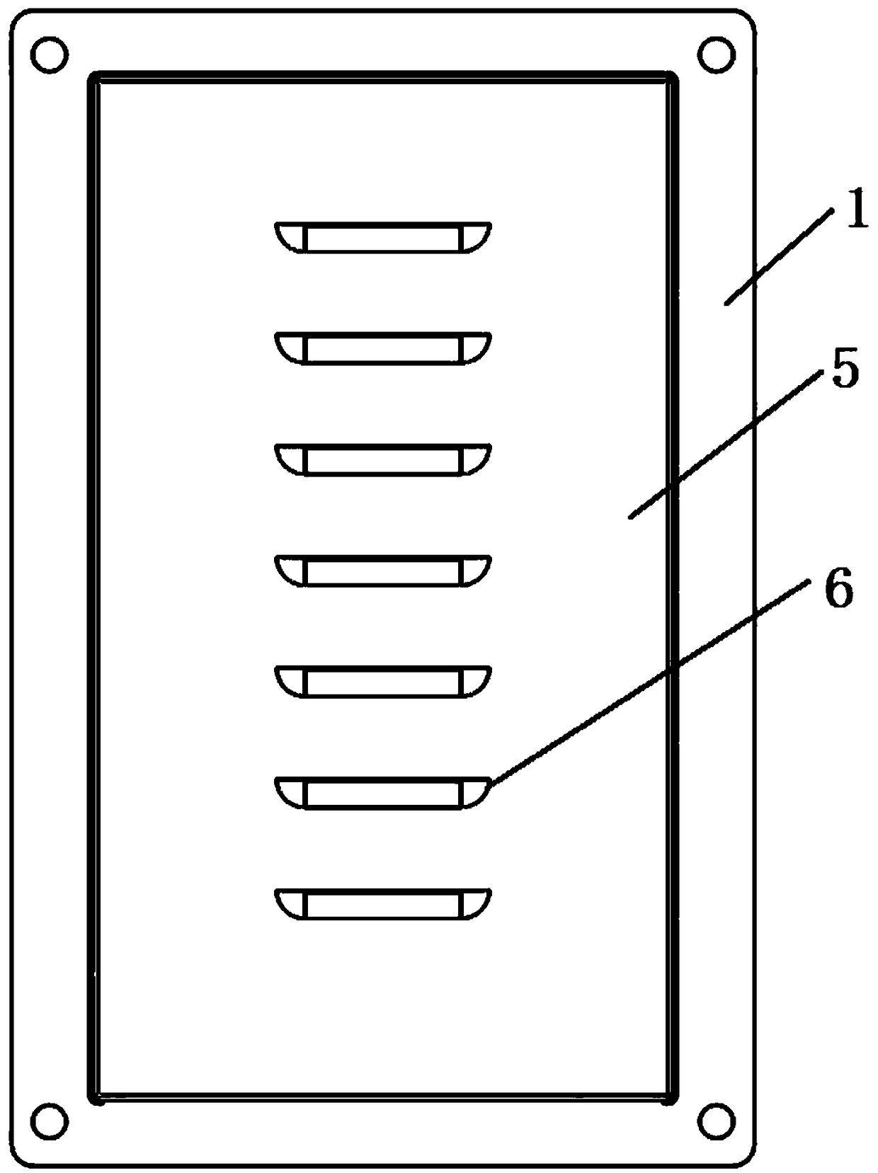
[0025] This embodiment provides a waterproof cover for a JP cabinet. The waterproof cover is made of ABS flame-retardant material with a grade of V-0. The basic design idea is that the front of the waterproof cover is flat and raised, and the side is a wedge-shaped structure with a narrow top and a wide bottom; ventilation louvers are designed on the front of the waterproof cover to increase ventilation and prevent splashing water.

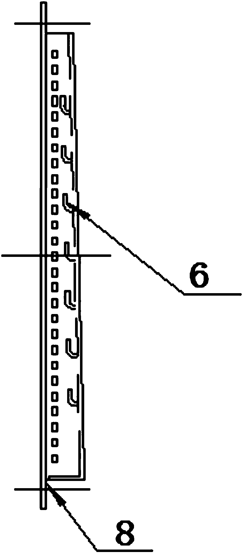
[0026] Specific structural design such as Figure 1-4 As shown, the waterproof cover includes a mounting plate 1, left and right side plates 3, an upper top plate 2, a lower bottom plate 7, and a cover plate 5. The left and right side plates 3 are wedge-shaped structures with a narrow top and a wide bottom, and the cover plate 5 is a flat plate. The first ventilation louvers 6 are arranged on the plate 5, and the first ventilation louvers 6 extend into the inner side of the cover plate 5 and are inclined upward.

[0027] The left and right side p...

Embodiment 2

[0030] like Figure 5-6 As shown, this embodiment provides a waterproof assembly for a JP cabinet, which includes a stainless steel mesh plate 9 and a side wall 10 of the JP cabinet in addition to the waterproof cover described in Embodiment 1. The waterproof cover is fixed on the inside of the side wall 10 of the JP cabinet through bolt fasteners (fastening bolts 12 and nuts 13), and the stainless steel mesh plate 9 is located between the waterproof cover and the side wall 10 of the JP cabinet, and is fixed to the JP cabinet by the flange of the waterproof cover. Cabinet side wall 10 inside. The stainless steel screen 9 adopts 304 stainless steel screen, the grid gap is less than or equal to 0.6mm, the stainless steel screen and the waterproof cover work together, and the protection level of the cabinet reaches IP44.

[0031] The second ventilation louver 11 is provided on the side wall 10 of the JP cabinet, and the second ventilation louver 11 stretches out from the outside...


PUM


Abstract

The invention discloses a water-proof cover and a water-proof assembly for a JP cabinet. The water-proof cover comprises a mounting plate, left and right side plates, an upper top plate, a lower bottom plate and a cover plate. The left and right side plates are of a wedge-shaped structure with an upper narrow and a lower wide, and the cover plate is a flat plate protruding, and a first ventilationlouver is arranged on the cover plate. The first ventilation louver extends into the inner side of the cover plate and is inclined upward. The waterproof component comprises a waterproof cover, a stainless steel mesh plate and a side wall of a JP cabinet, wherein a second ventilation louver is arranged on the side wall of the JP cabinet, and the second ventilation louver protrudes from the outside of the side wall of the JP cabinet and is inclined downward; The first ventilation louver and the second ventilation louver are staggered with each other to form a labyrinth ventilation duct, whichcan meet ventilation requirements and has good waterproof effect.

Description

technical field [0001] The invention belongs to the technical field of transformers, and relates to a waterproof device used in a JP cabinet of a 10kV pole-mounted transformer platform, in particular to a waterproof cover and a waterproof component for the JP cabinet. Background technique [0002] Now the State Grid Corporation clearly requires IP44 for the protection level of the JP cabinet of the 10kV pole-mounted transformer platform, and the temperature rise should meet the requirements of GB7251.12. This requires that the JP cabinet not only has good ventilation and air volume, but also has a high standard of waterproof and dustproof performance. In order to meet this requirement, ventilation louvers are generally installed on the side wall of the JP cabinet. The traditional scheme of spot-welding stainless steel mesh inside the louvers has sufficient ventilation, but there is a risk of water leakage in the 180° water spray test. Some companies install additional louver...

Claims


Application Information

Patent Timeline
Patent Type & Authority Applications(China)
IPC IPC(8): H05K5/02H05K7/20
CPCH05K5/0217H05K7/20H05K5/03
Inventor 周君张善文吕东明沈波高美华
Owner QINGDAO TGOOD ELECTRIC
Learn More