Eureka AIR delivers breakthrough ideas for toughest innovation challenges, trusted by R&D personnel around the world.

Quick pressure head flange for compressor motor

A compressor and pressure loading technology, which is applied in the direction of mechanical equipment, connecting components, etc., can solve the problems of increasing time cost, time-consuming and laborious replacement of pressure heads, etc., and achieve the effect of saving time and improving production efficiency

Pending Publication Date: 2019-01-15
ZHEJIANG MICROMACRO ITO TECH CO LTD
View PDF0 Cites 0 Cited by
  • Summary
  • Abstract
  • Description
  • Claims
  • Application Information

AI Technical Summary

Problems solved by technology

[0002] Compressors are used more and more widely. Due to the unreasonable mechanism design of the pressure head in the current compressor motor, there is a big problem in the replacement of the pressure head.
The replacement of the current indenter is time-consuming and labor-intensive, resulting in increased time and equipment costs

Method used


Image

  • Quick pressure head flange for compressor motor
  • Quick pressure head flange for compressor motor

Examples


Embodiment Construction

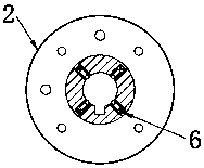
[0010] Combine below figure 1 and figure 2 Specific description embodiment:

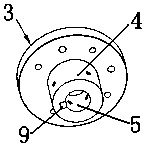
[0011] The quick-install pressure head flange of the compressor motor includes a flange base 3 and a pressure head seat 4. The flange base is fixed on the guide plate, and the pressure head seat is provided with a pressure head placement groove 5. Several ball plungers 6 are arranged on the inner wall of the indenter seat, and the ratio of the depth of the indenter seating groove to the height of the indenter seat is 2:3.

[0012] Further, the inner side of the indenter seat is provided with a positioning keyway 9 .

[0013] Further, the indenter placement groove is a cylindrical groove.

[0014] In specific use, the flange of the indenter is positioned and fixed on the guide plate by screws and pins. The indenter placement groove of the indenter flange is provided with a positioning keyway, which is used for the indenter that requires angular positioning. The positioning keyway does not require ...


PUM


Abstract

The invention belongs to the technical field of compressor tools, and particularly relates to a quick pressure head flange for a compressor motor. The quick pressure head flange for the compressor motor comprises a flange base and a pressure head base, wherein the flange base is fixedly arranged on a guide pressure plate; a pressure head mounting slot is formed in the pressure head base; a plurality of ball head plunger pistons are arranged on the inner wall of the pressure head base; and a ratio of depth of the pressure head mounting slot to height of the pressure head base is 2 to 3. The quick pressure head flange has the beneficial effects of having a floating function and an angle orientating function, greatly improving production efficiency, saving time and equipment cost while guaranteeing a pressing process.

Description

technical field [0001] The invention belongs to the technical field of compressor appliances, in particular to a quick-install pressure head flange of a compressor motor. Background technique [0002] Compressors are used more and more widely, and the pressure head in the current compressor motor is unreasonably designed, so there is a big problem in the replacement of the pressure head. The replacement of the current indenter is time-consuming and laborious, thus resulting in increased time and equipment costs. Contents of the invention [0003] The purpose of the present invention is to solve the above-mentioned technical problems, to provide a compressor motor with a floating function and an orientation angle function, which greatly improves the production efficiency, ensures the press-fitting process, and saves time and equipment costs. The technical scheme of the quick-install pressure head flange is as follows: [0004] The quick-install pressure head flange of the...

Claims


Application Information

Patent Timeline
IPC IPC(8): F16B21/12
CPCF16B21/12
Inventor 钱杰金大峰王琪
Owner ZHEJIANG MICROMACRO ITO TECH CO LTD
Why Eureka
Eureka Blog
Learn More