
Fracture reduction expander

A technology of spreaders and limit protrusions, applied in fixers, external fixators, medical science, etc., to achieve good rigidity and stability, avoid unnecessary injuries and blocking, and have good fixation effects

Pending Publication Date: 2019-01-15
范士洁
View PDF11 Cites 0 Cited by
  • Summary
  • Abstract
  • Description
  • Claims
  • Application Information

AI Technical Summary

Problems solved by technology

[0003] The purpose of the present invention is to provide a fracture reduction spreader to solve the problems existing in the existing orthopedic traction tools

Method used


Image

  • Fracture reduction expander
  • Fracture reduction expander
  • Fracture reduction expander

Examples


Embodiment

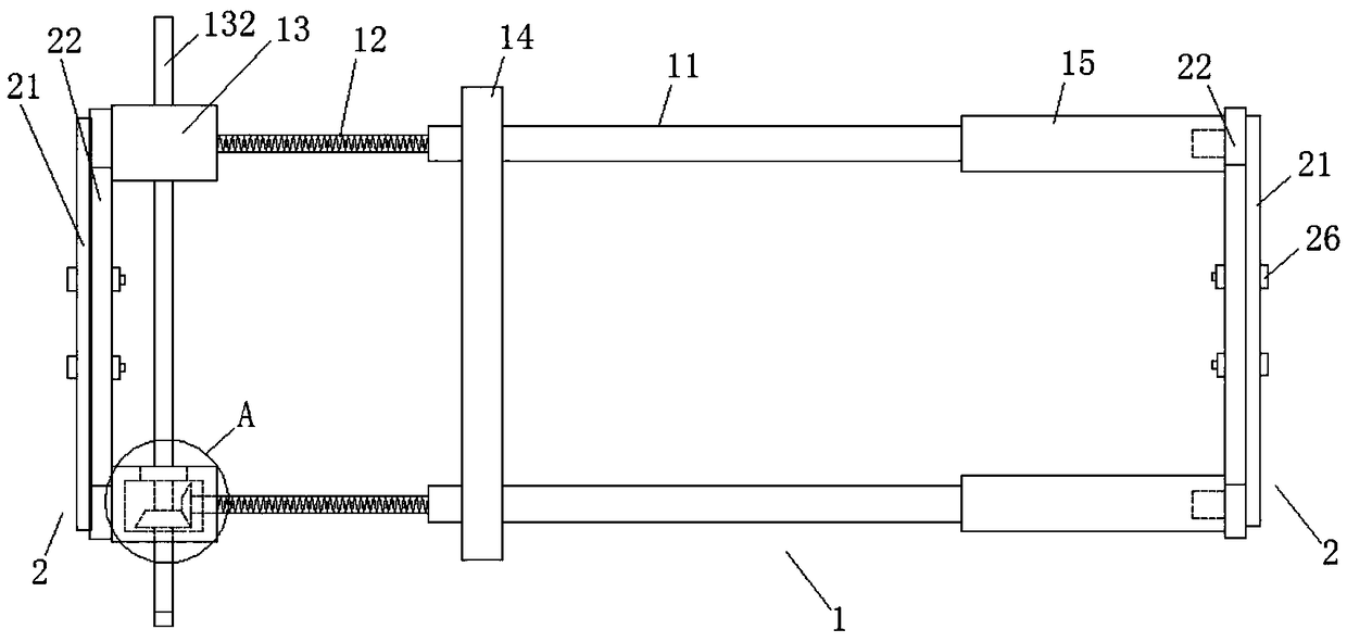
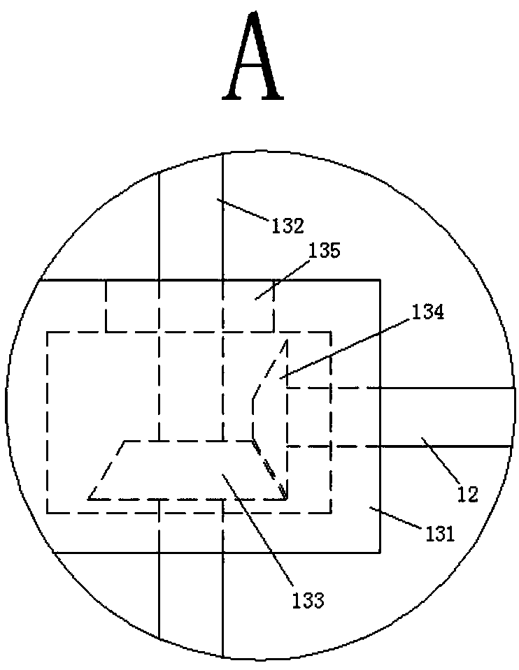
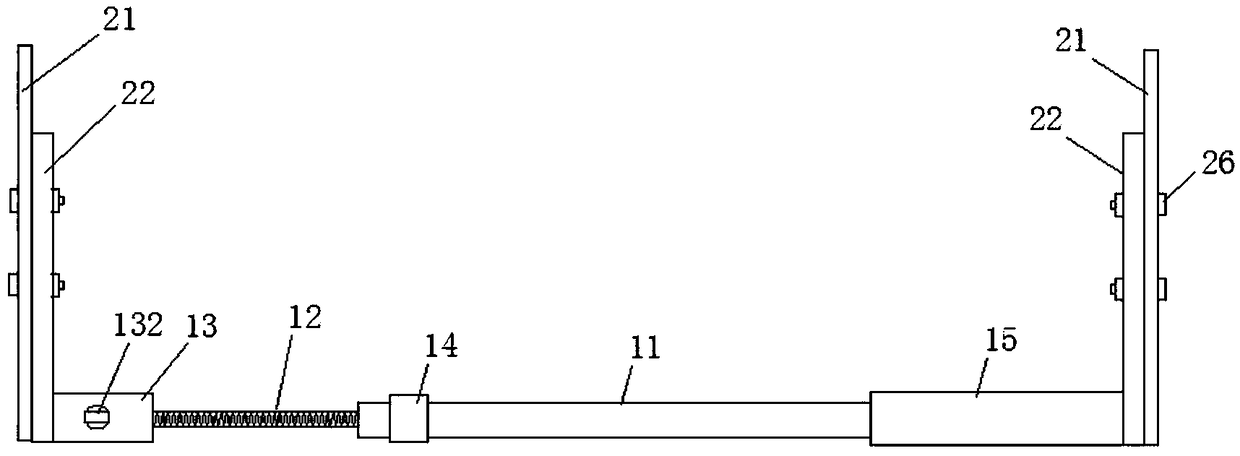
[0027] refer to Figure 1 to Figure 6 , the present embodiment provides a fracture reduction spreader, comprising a screw slide rail spreading device 1 and traction needle holders 2 respectively fixed to the two ends of the screw slide rail spreading device 1, and the screw slide rail spreading device 1 It is a parallel double guide screw structure, and the parallel double guide screw structure is synchronously telescopic and tractive, and the traction needle fixing frame 2 is fixed on both ends of the screw slide rail spreading device 1 .

[0028] Screw slide rail expansion device 1 includes two guide rods 11 and threaded rods 12 parallel to each other. One end of the rod 11 is provided with a threaded hole along the length direction, one end of the threaded rod 12 is screwed in the threaded hole on the guide rod 11, and the other end of the threaded rod 12 is correspondingly provided with a driving mechanism 13, and the driving mechanism 13 includes a gear box 131 and the d...


PUM


Abstract

A fracture reduction expander comprises a screw rail expanding device and a traction pin fixing frame fixed at both ends of the screw rail expanding device, wherein the screw rail expanding device isof a parallel double-guide rod type structure, and the parallel double-guide rod type structure is synchronously pulled, and the traction pin fixing frame is fixed at both ends of the screw rail expanding device. As that exist traction and expanding tools or structure are complex, tedious to operate, or single in function, and the structure design is unreasonable, the expanding and distraction force are not consistent with the physiological force line, the angle is formed and the reduction deformity is cause, the expanding and distraction are all monorail traction, the synchronous traction ofthe two rails is difficult to realize, and the distraction and distraction and distraction and distraction reduction effect are poor. The invention belongs to the field of orthopaedic traction.

Description

technical field [0001] The invention relates to a fracture reduction spreader, which belongs to the field of orthopedic treatment. Background technique [0002] At present, in the existing fracture reduction and correction treatment, it is often necessary to use a spreader to perform traction and distraction reduction on the fracture site. The existing traction and distraction tools or structures are relatively complicated, the operation is cumbersome, or the function is single, and the structural design is unreasonable. Or the direction of distraction and traction is inconsistent with the physiological force line, resulting in angulation and reduction deformity. The unreasonable setting of the main structure of the existing tools will affect the operation during the operation, and then need to prolong the wound, increase the bleeding, prolong the operation time, and cause further harm to the patient; in addition, the existing tools will block X-ray shooting and affect X-ray...

Claims


Application Information

Patent Timeline
Patent Type & Authority Applications(China)
IPC IPC(8): A61B17/02A61B17/66
CPCA61B17/025A61B17/6425A61B17/66A61B2017/564
Inventor 范士洁赵滨杨晓秋乔俊钊吕信息杨胜强
Owner 范士洁
Learn More