
Window ascending-descending device

A lifting device and window technology, applied in the layout of wings, door/window accessories, buildings, etc., can solve the problems of reducing the overall space use efficiency, not conforming to the original design intention of the building, and affecting the indoor layout, etc., to achieve accurate movement Reliable, flexible and light operation, and accurate window movement

Inactive Publication Date: 2019-01-11
HEILONGJIANG AGRI MACHINERY REPAIR INST
View PDF13 Cites 2 Cited by
  • Summary
  • Abstract
  • Description
  • Claims
  • Application Information

AI Technical Summary

Problems solved by technology

For ordinary homes or buildings, there are no special restrictions on the opening and closing methods of the windows. The common structures are mostly a hinge mechanism on one side of the window, which is used as the axis to realize fan-shaped opening, and the opening can be of any size. Adjustable, there is also a structure that can be used as shafts on both sides, but the opening is greatly limited, and it is generally used in places subject to safety restrictions
However, in special occasions such as the sunshine hall of buildings and the sunshine greenhouse of facility agriculture, due to the large window, if the traditional hinge structure is adopted, if the window is required to be fully opened, due to the full range of opening and closing strokes, it will be It is required to leave a large space indoors, so that the use of the space near the window will be limited, which not only affects the interior layout, reduces the efficiency of the overall space use, but also affects the appearance, which is obviously not suitable for this type of building This is the original intention of the design, which is some disadvantages and limitations of the current traditional hinge structure to open and close the window

Method used


Image

  • Window ascending-descending device
  • Window ascending-descending device
  • Window ascending-descending device

Examples


Embodiment Construction

[0023] The present invention will be described in detail below in conjunction with the accompanying drawings.

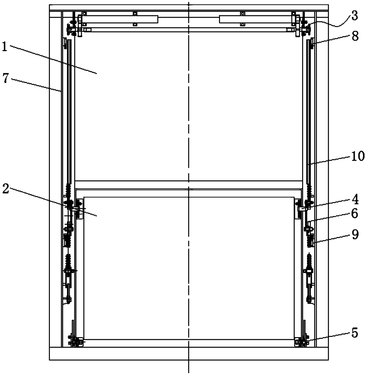
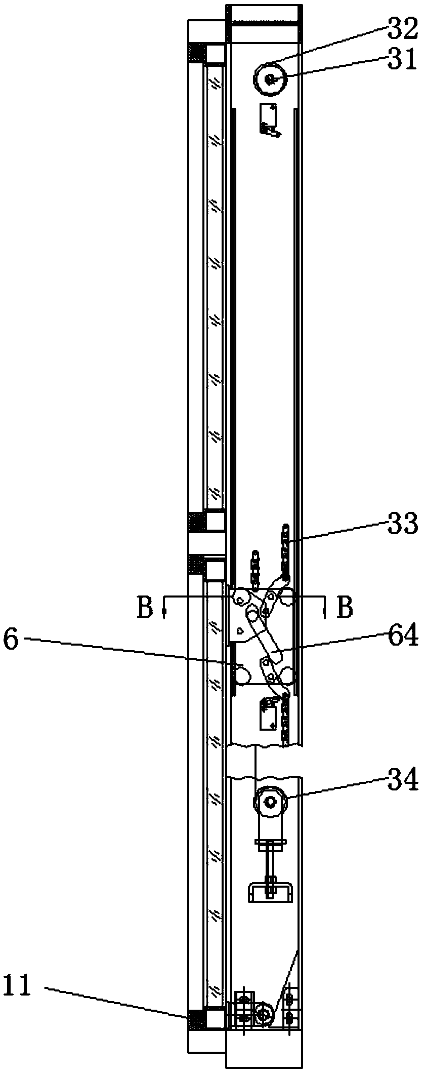
[0024] combine Figure 1-Figure 8 As shown, a window lifting device disclosed in this embodiment includes: a fixed glass window 1, a movable glass window 2, a drive system 3, an upper suspension shaft 4, a lower roller shaft 5, a traveling vehicle 6, and an H beam cavity 7 The fixed glass window 1 is fixedly arranged on the wall, the movable glass window 2 is arranged under the fixed glass window 1, and a group of upper suspension shafts are respectively arranged on the left and right sides of the upper end surface of the movable glass window 2 4. The other ends of the two upper suspension shafts 4 are respectively arranged on a group of trolleys 6, and the trolleys 6 are set in the track grooves 10 in the H-beam cavity 7, and the H-beam cavity 7 is fixed Set on the wall, the movable glass window is set inside the H-beam cavity 7, the trolley 6 is also connected wit...


PUM


Abstract

The invention relates to the technical field of window ascending and descending, in particular to a window ascending-descending device. The window ascending-descending device comprises a fixed glass window body; the fixed glass window body is fixedly disposed in a wall surface; a movable glass window body is disposed below the fixed glass window body; upper suspension shafts are disposed on the left side and the right side of the upper end surface of the movable glass window body correspondingly; the other ends of the two upper suspension shafts are disposed on travelling trolleys correspondingly; the travelling trolleys are disposed in track grooves in an H-beam cavity; the H-beam cavity is fixedly disposed on the wall surface; the movable glass window body is disposed in the H-beam cavity; the travelling trolleys are connected with driving systems in a matched mode; and the driving systems are disposed above the fixed glass window body. By means of the window ascending-descending device, the glass wall can keep a relatively independent environment characteristic, which a common building wall structure is supposed to achieve, of the indoor space and the outside and can extremely conveniently achieve indoor and outside communication through local movement so as to achieve the comfortable state that people and nature are integrated.

Description

technical field [0001] The invention relates to the technical fields of construction machinery and agricultural machinery, in particular to a window lifting device. Background technique [0002] Existing buildings, including building sunshine halls, sunshine greenhouses for facility agriculture, etc., all need to be equipped with movable glass windows that can be opened and closed to allow indoor and outdoor air circulation, or to directly feel and get close to nature indoors. For ordinary homes or buildings, there are no special restrictions on the opening and closing methods of the windows. The common structures are mostly a hinge mechanism on one side of the window, which is used as the axis to realize fan-shaped opening, and the opening can be of any size. Adjustable, there is also a structure that can be used as shafts on both sides, but the opening is greatly limited, and it is generally used in places subject to safety restrictions. However, in special occasions such...

Claims


Application Information

Patent Timeline
Patent Type & Authority Applications(China)
IPC IPC(8): E05F15/665E06B3/44
CPCE05F15/665E05Y2900/148E06B3/44
Inventor 李树军刘庆余李国民郝磊赵萍李子奇
Owner HEILONGJIANG AGRI MACHINERY REPAIR INST
Learn More