
A bridge support and its installation method

A bridge bearing and bearing plate technology, applied in bridges, bridge construction, bridge parts, etc., can solve the problems of complex use of bridges and indeterminate horizontal displacement directions, so as to improve the service life, weaken the force, and increase the adaptability. Effect

Active Publication Date: 2020-04-24
四川志德公路工程有限责任公司
View PDF7 Cites 0 Cited by
  • Summary
  • Abstract
  • Description
  • Claims
  • Application Information

AI Technical Summary

Problems solved by technology

[0004] Its shortcoming is that the track is a straight track, so that the horizontal sliding between the middle liner and the upper support plate can only be realized in the same straight line direction, but the actual use of the bridge is more complicated, and the direction of the horizontal displacement caused by vibration is uncertain , there are certain limitations

Method used


Image

  • A bridge support and its installation method
  • A bridge support and its installation method
  • A bridge support and its installation method

Examples


Embodiment 1

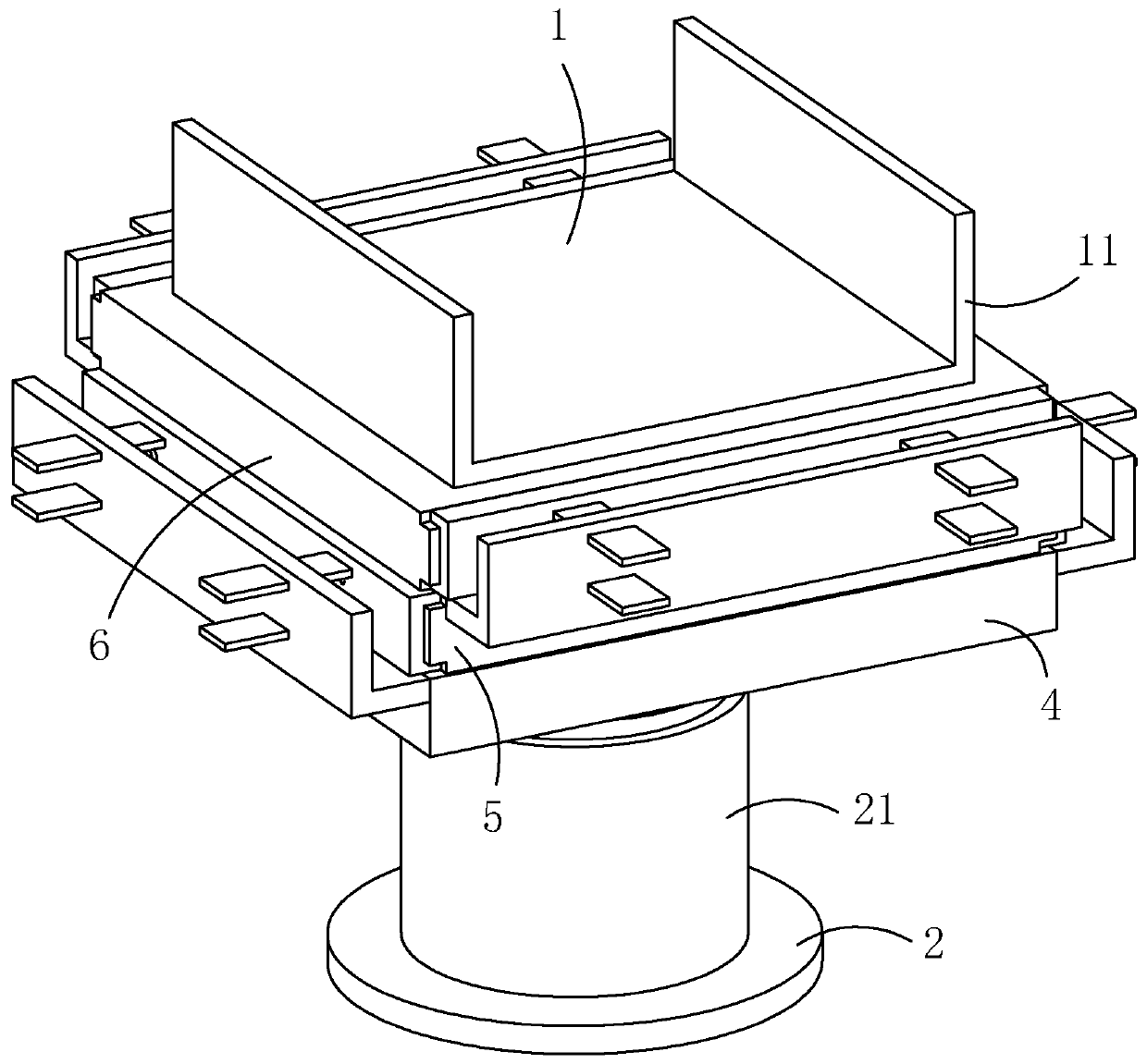
[0046] Such as figure 1 , 2 As shown, a bridge bearing includes an upper bearing plate 1 connected to the bridge girder body, on which the upper bearing plate 1 is fixedly connected with a pre-embedded steel plate 11, two pre-embedded steel plates 11 are arranged, and are connected to the lower support of the bridge pier The seat plate 2 and the rubber bearing 3 arranged between the upper support plate 1 and the lower support plate 2 (see Figure 4 ), also includes a support plate 4 , a first slide plate 5 and a second slide plate 6 , and the support plate 4 is arranged on the rubber support 3 .

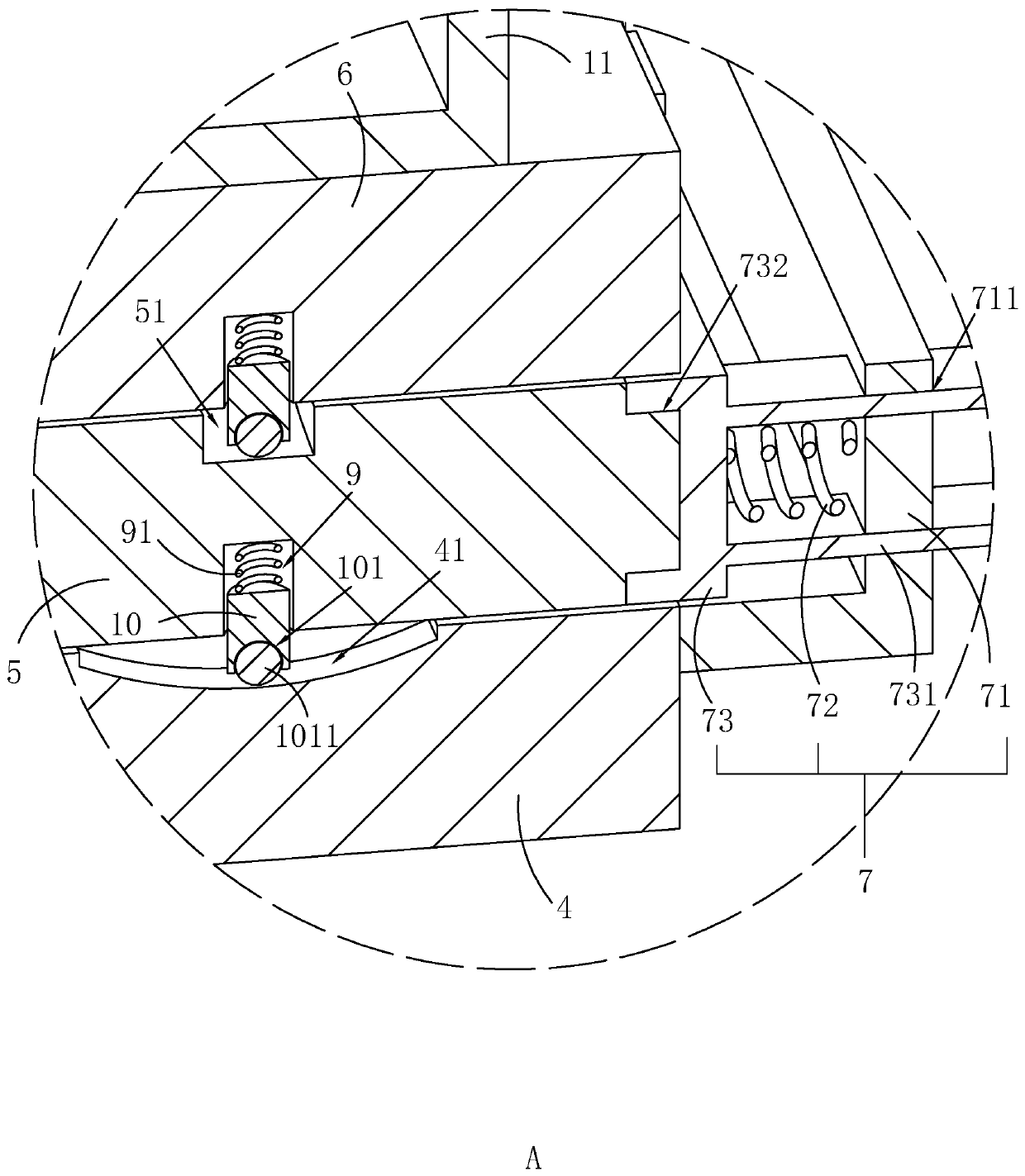
[0047] Such as figure 2 , 3 As shown, the upper surface of the support plate 4 is provided with a first guide groove 41, the first slide plate 5 is slidably arranged on the support plate 4, and the first slide plate 5 is provided with a first sliding connection with the first guide groove 41. Sliding part; the second sliding plate 6 is slidably arranged on the first sliding plat...

Embodiment 2

[0059] A method for installing a bridge support, comprising the following steps:

[0060] Step 1. The pre-embedded steel plate 11 of the bridge girder body is installed. First, according to the number and layout position of the rubber bearings 3 set on the bridge pier, during the prefabrication process of the bridge girder body, each rubber bearing 3 is pre-embedded at the bottom of the bridge girder body. The pre-embedded steel plate 11 at the bottom of the beam;

[0061] Step 2. Install the rubber support 3, install the lower support plate 2 on the pier, then install the rubber support 3 on the lower support plate 2, and then install the support plate 4, the first movable plate and the second movable plate in sequence , through the laser locator for installation and positioning to ensure the accuracy of the installation;

[0062] Step 3, drop the beam, hoist the bridge beam body with the pre-embedded steel plate 11 embedded at the bottom, and drop the bridge beam body until...


PUM


Abstract

The invention relates to a bridge bearing, belonging to the technical field of road and bridge, comprising a support plate, a first sliding plate and a second sliding plate. The support plate is arranged on a rubber support. The upper surface of the support plate is provided with a first guide groove. The first sliding plate is slidably arranged on the support plate. The second sliding plate is slidably arranged on the first sliding plate, and the upper surface of the first sliding plate is provided with a second guide groove perpendicular to the first guide groove, and the second sliding plate is provided with a second sliding part slidably connected with the second guide groove. The support plate is provided with a first reset assembly for driving the first sliding plate to reset, and the first sliding plate is provided with a second reset assembly for driving the second sliding plate to reset. The support plate, the first sliding plate and the second sliding plate are matched, so that the second sliding plate can slide in any horizontal direction relative to the supporting plate, thereby meeting the horizontal displacement requirements of the bridge in different directions and increasing the adaptability.

Description

technical field [0001] The invention relates to the technical field of road bridges, in particular to a bridge support and an installation method thereof. Background technique [0002] Bridge bearings are important components that connect and constrain bridge girders and piers, and their interactions with girders and piers are quite complex, for example, including the transfer of constant loads and live loads to piers and foundations, as well as the completion of girder structures. The required deformation, horizontal displacement and rotation angle, therefore, the bearing is very important for the bridge. The difference in bearings often affects the force transmission between the upper and lower structures of the bridge, thereby affecting the overall structure of the bridge. [0003] The Chinese invention patent with the authorized notification number CN106758792B discloses a bridge support, which includes an upper support plate and a lower support plate. The upper support...

Claims


Application Information

Patent Timeline
Patent Type & Authority Patents(China)
IPC IPC(8): E01D19/04
CPCE01D19/042
Inventor 刘毅曾礼德黄世全周娟陈健
Owner 四川志德公路工程有限责任公司
Learn More