Rotogravure with snubber roll

A technology of gravure printing and printing mechanism, which is applied to gravure rotary printing machines, printing machines, rotary printing machines, etc. It can solve the problems of lost settings, web tension changes, etc., and achieve good registration accuracy and fast adjustment effects

Inactive Publication Date: 2019-01-04
HEIDELBERGER DRUCKMASCHINEN AG
View PDF2 Cites 2 Cited by
  • Summary
  • Abstract
  • Description
  • Claims
  • Application Information

AI Technical Summary

Problems solved by technology

[0005] It is also disadvantageous that the web tension is changed when adjusting the position of the plate cylinder in case the printing register needs to be corrected
In each case of stopping the gravure printing press with the lifting of the pressure roller, the set-up in register is lost

Method used


Image

  • Rotogravure with snubber roll
  • Rotogravure with snubber roll
  • Rotogravure with snubber roll

Examples


Embodiment Construction

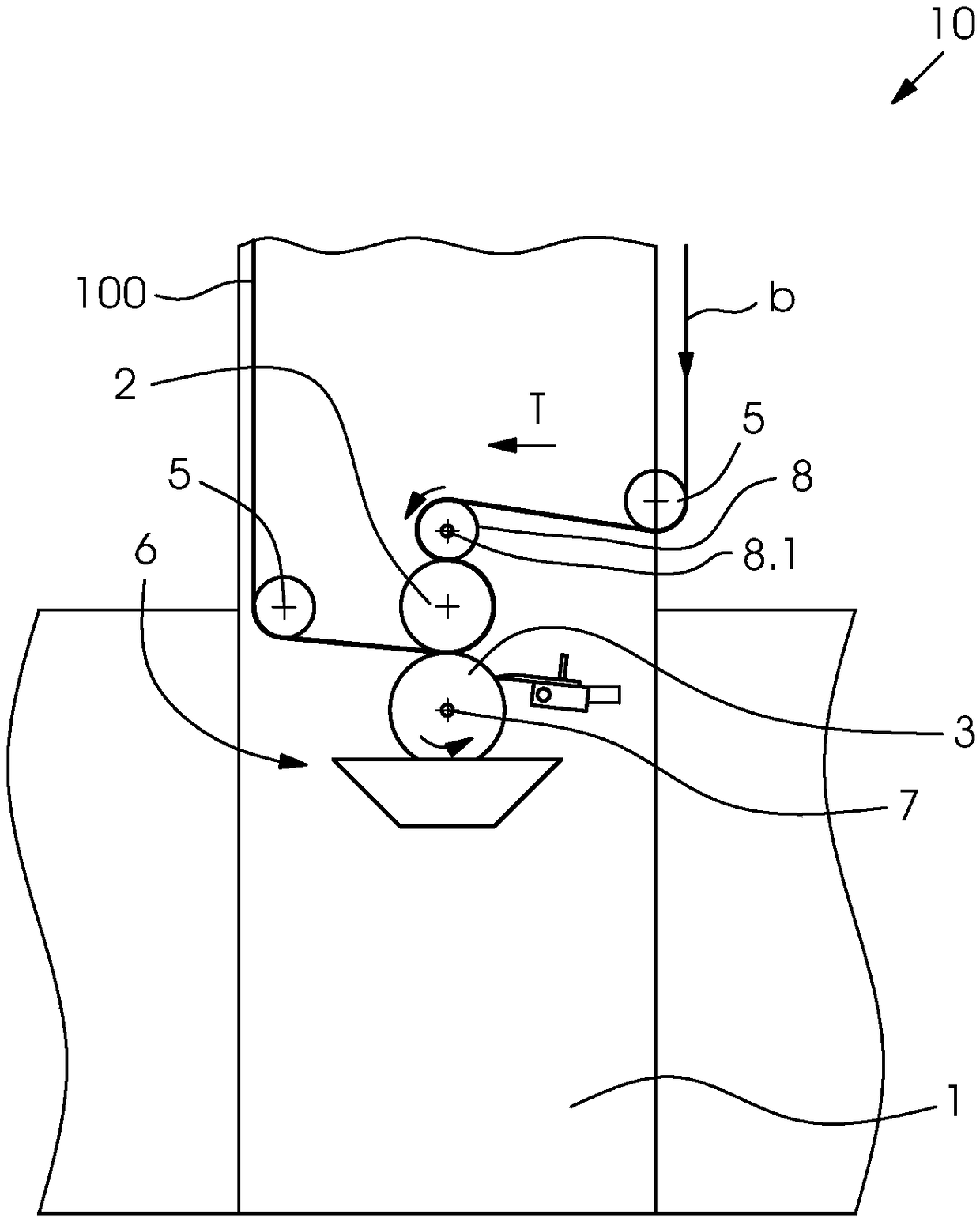
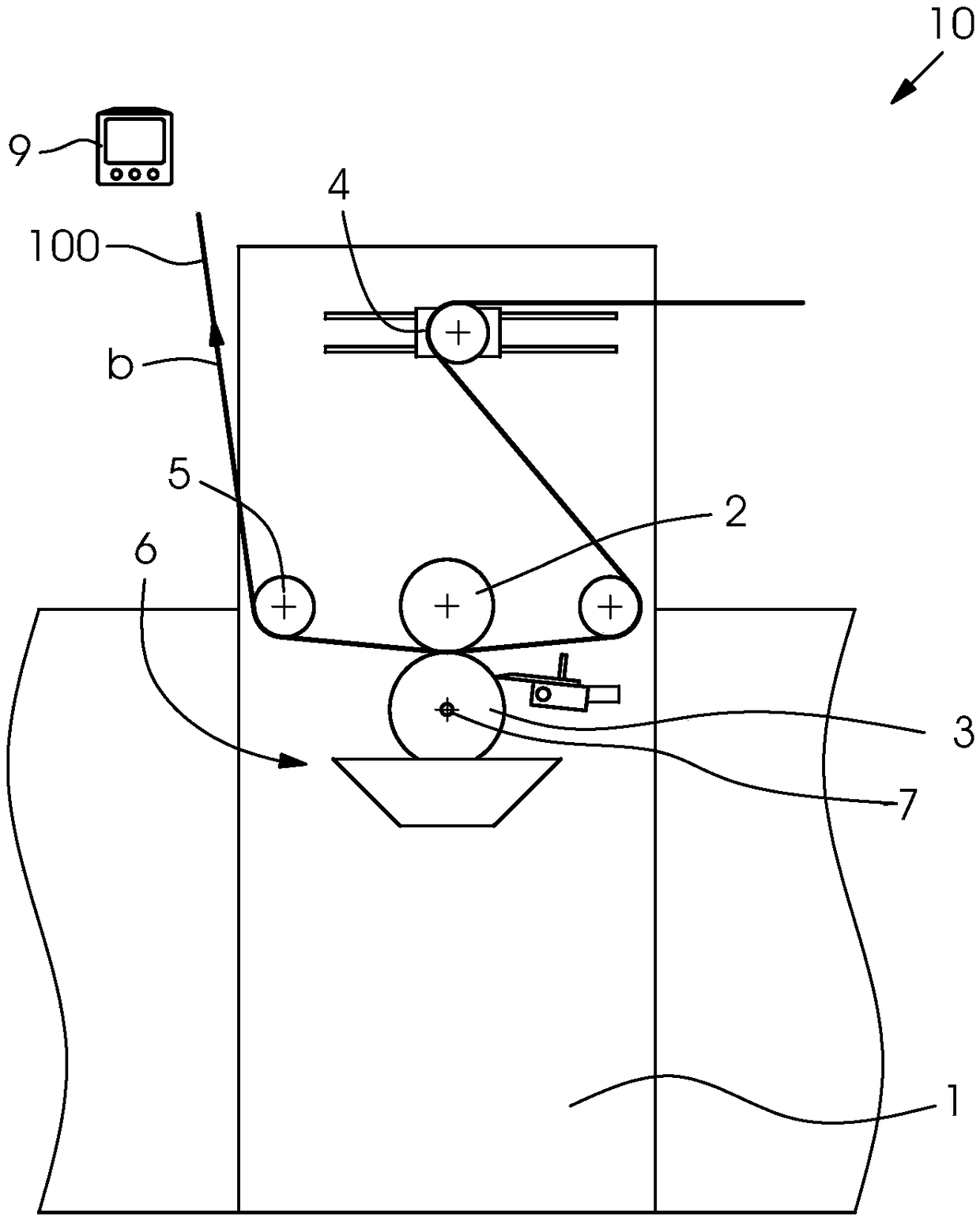
[0027] exist image 3 A rotogravure printing unit 10 according to the prior art is shown in , in which a printing material web 100 is printed. The support structure of the printing unit 10 is formed by the printing unit carrier 1 . As indicated by the arrow b, the printing material web 100 runs through the rotogravure printing unit 10 in such a way that the printing material web 100 passes through a not-shown pre-printing unit or pre-processing station via the web The belt tension compensation device 4 enters the gravure printing mechanism 10, and the printing material web 100 is guided through the gravure printing cylinder 3 and the pressure roller 2 by the first guide roller 5 (here the printing material web 100 is printing), and then, before the printing material web 100 leaves the gravure printing mechanism 10 and is further conveyed to a subsequent, not-shown further printing mechanism or a subsequent, not-shown processing station, the printed The material web 100 is ...


PUM


Abstract

A rotogravure unit 10 of a printing machine for printing on a web-shaped printing material 100 includes a forme cylinder 3, an ink application device 6, an impression cylinder 2 and guide rollers 5 for guiding the printing material 100. A driven pull roller 8 and a further roller 2, 12 form a roller pair for transporting the printing material 100. The rotogravure unit advantageously permits only afew waste products to be created when the machine is started up or restarted and in-register printing is made quickly possible.

Description

technical field [0001] The invention relates to a rotogravure printing unit having the features stated in the preamble of claim 1 . Background technique [0002] A configuration of a rotogravure printing unit is given, for example, in document EP 2 604 431 B1. The circumferential surface of the gravure printing cylinder (hereinafter also referred to simply as printing cylinder, gravure printing cylinder or printing cylinder) is at least partially sunk in an ink pan filled with gravure printing ink, which is arranged in the Below the gravure plate cylinder. During rotation of the intaglio printing cylinder about its axis of symmetry, those depressions in the peripheral surface which pass through the disc grooves are filled with intaglio printing ink. [0003] Excess ink is wiped off by at least one doctor blade pressed against said peripheral surface. In the printing nip located in the upper corner section of the gravure printing cylinder, the gravure printing ink is trans...

Claims


Application Information

Patent Timeline
Patent Type & Authority Applications(China)
IPC IPC(8): B41F9/00B41F9/06B41F13/02
CPCB41F9/003B41F9/06B41F13/02B41F9/00B41F9/18B41M1/10
Inventor H·沙德尔
Owner HEIDELBERGER DRUCKMASCHINEN AG
Why Eureka
Try Eureka