
A spring feeding device

A technology of feeding device and hopper, applied in the field of automobile headrest duct production equipment, can solve the problems of low work efficiency, high labor intensity, and many manual interventions, so as to achieve high work efficiency, improve efficiency, and realize the effect of automatic feeding

Active Publication Date: 2020-07-17
CHONGQING ZHENGZE AUTOMOBILE PARTS
View PDF8 Cites 0 Cited by
  • Summary
  • Abstract
  • Description
  • Claims
  • Application Information

AI Technical Summary

Problems solved by technology

[0004] In the prior art, the assembly of the headrest catheter is mostly completed in a semi-automatic working environment. The main body of the catheter and the buckle are fixed to the two stations of the working platform by manual clamping and loading, and then the buckle is fixed on the two stations. Install the spring and bayonet, and finally install the buckle on the main body of the catheter. There are many manual interventions in the whole process, which is labor-intensive and low-efficiency.

Method used


Image

  • A spring feeding device
  • A spring feeding device
  • A spring feeding device

Examples


Embodiment Construction

[0026] Embodiments of the technical solutions of the present invention will be described in detail below in conjunction with the accompanying drawings. The following examples are only used to illustrate the technical solutions of the present invention more clearly, and therefore are only examples, rather than limiting the protection scope of the present invention. In the description of the present application, it should be understood that the orientation or positional relationship indicated by the terms "upper", "lower", "front", "rear", etc. is based on the orientation or positional relationship shown in the accompanying drawings, only It is for the convenience of describing the present invention and simplifying the description, but does not indicate or imply that the components or structures referred to must have a specific orientation, be constructed and operated in a specific orientation, and thus should not be construed as limiting the present invention.

[0027] Such as ...


PUM


Abstract

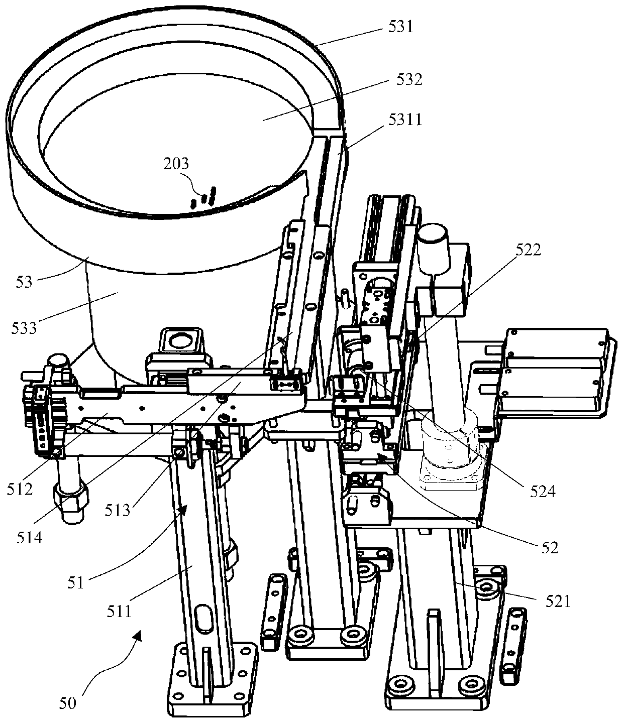
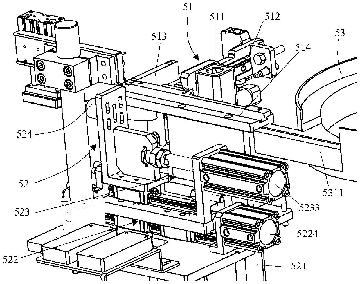
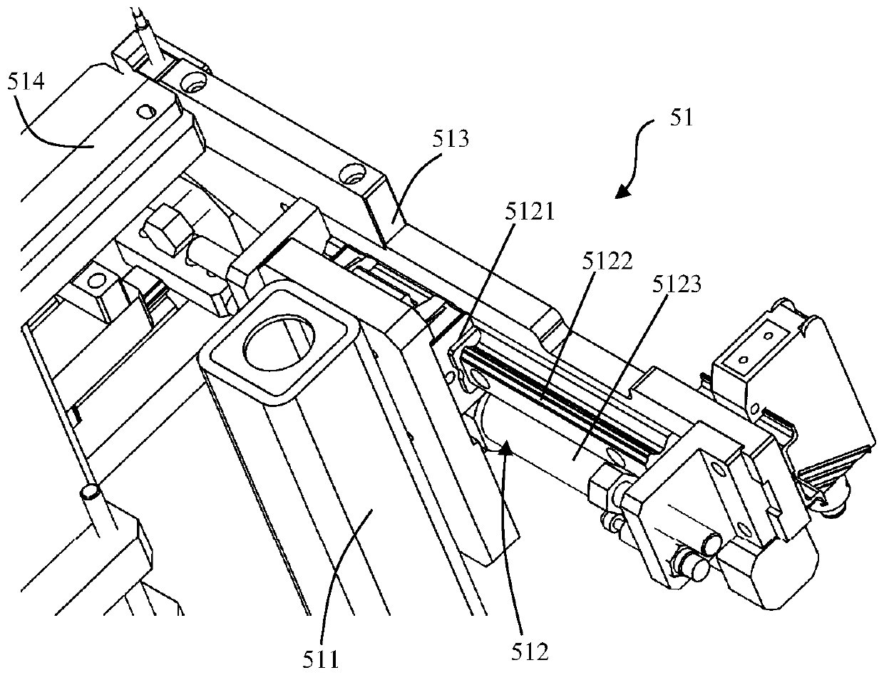
The invention discloses a spring feeding device. The spring feeding device comprises a spring arranging device, a lateral feeding device and a feed feeding device, wherein the spring arranging deviceenables springs to sequentially flow out of a spring output port in a uniform posture; the lateral feeding device and the feed feeding device are arranged at two sides of the spring output port respectively; the lateral feeding device comprises a material receiving plate provided with a spring accommodating hole, and a lateral moving mechanism for driving the material receiving plate to move linearly in the horizontal direction; and the feed feeding device comprises a feeding mechanism and a reclaimer mechanism arranged on the feeding mechanism, the feeding mechanism moves horizontally and linearly perpendicular to the moving direction of the lateral moving mechanism to acquire a spring in the spring accommodating hole and transmit and mounting the spring on a buckle. The spring feeding device can realize automatic feeding of the spring to a working table and the assembly with the buckle, and has the advantages of automatic operation in the whole process, simple process and operation,and high working efficiency.

Description

technical field [0001] The invention relates to the field of automobile headrest conduit production equipment, in particular to a spring feeding device. Background technique [0002] With the development of the automobile industry, people have higher and higher requirements for car comfort. Seats are the direct carrier of car ride comfort, and the comfort of use is particularly important. Headrests are an indispensable part of car seats. , which can be easily installed and adjusted, is an important reference feature for the comfort experience of car seats. [0003] At present, the installation of the car seat headrest mainly adopts the headrest conduit on the back of the seat, and the headrest is inserted and fixed in the headrest conduit through the headrest rod at its lower part; for the convenience of installation and adjustment of the headrest, the headrest The specific structure of the pillow catheter includes: the main body of the catheter, buckles, springs and bayone...

Claims


Application Information

Patent Timeline
Patent Type & Authority Patents(China)
IPC IPC(8): B23P19/00
CPCB23P19/001
Inventor 蹇钢
Owner CHONGQING ZHENGZE AUTOMOBILE PARTS
Learn More