
Water-containing plate assembly and lower air outlet machine room air conditioner

A technology of water trays and components, applied in air conditioning systems, prevention of condensed water, space heating and ventilation, etc., can solve the problems of large pressure difference, unable to discharge in time, and affect the normal operation of the machine, so as to facilitate collection and improve replacement The effect of thermal efficiency

Active Publication Date: 2018-11-30
青岛海信网络能源股份有限公司
View PDF6 Cites 2 Cited by
  • Summary
  • Abstract
  • Description
  • Claims
  • Application Information

AI Technical Summary

Problems solved by technology

However, in a large computer room air conditioning system, due to the large pressure difference on both sides of the heat exchanger and the high wind speed on the surface of the heat exchanger, there is a gap between the bottom of the heat exchanger fin and the supporting structure, which will generate horizontal airflow, perpendicular to the condensed water In the direction of movement, the blowing condensate accumulates at the root of the inner flange of the drain pan and cannot be discharged in time. Blow out the water tray and enter the inside of the machine, thus affecting the normal operation of the machine

Method used


Image

  • Water-containing plate assembly and lower air outlet machine room air conditioner
  • Water-containing plate assembly and lower air outlet machine room air conditioner
  • Water-containing plate assembly and lower air outlet machine room air conditioner

Examples


Embodiment Construction

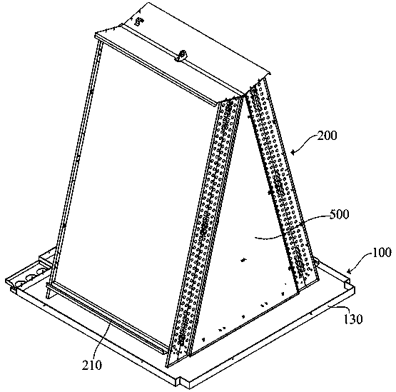
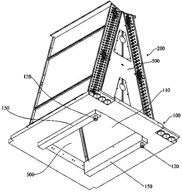
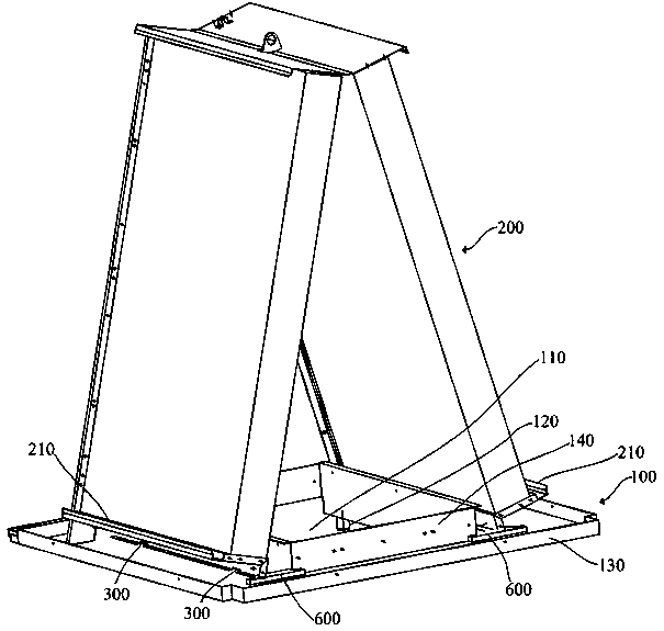
[0028] The specific implementation manners of the present invention will be further described in detail below in conjunction with the accompanying drawings.

[0029] Such as Figure 1 to Figure 6 As shown, a water tray assembly in this embodiment includes a water tray body 100 and a heat exchanger 200, the heat exchanger 200 is installed on the water tray body 100 with its bottom end, and the water tray body 100 is provided with Ventilation holes 110 and drain ports 120, the surrounding edges of the water tray body 100 have upwardly turned outward flanges 130, the surrounding edges of the ventilation holes 110 are provided with upwardly folded internal flanges 140, and the lower end of the heat exchanger 200 is located at The outside of the inner flange 140; different from the prior art, the water receiving tray body 100 in this embodiment is also provided with a water storage groove 150 that is sunken downward relative to the water receiving tray body 100, and the water outle...


PUM


Abstract

The invention provides a water-containing plate assembly and a lower air outlet machine room air conditioner. Condensed water can be effectively collected, and the condensed water in a water-containing plate assembly is prevented from being blown into the air conditioner by wind as much as possible. The water-containing plate assembly and a heat exchanger are installed on a water-containing platebody, the water-containing plate body is provided with a ventilation hole, a water discharging port and a water storage groove. The water discharging port is communicated with the water storage groove. The water storage groove is located in the outer side of an inner flanged edge and the leeward side of the lower end of the heat exchanger, the part, in contact with the water-containing plate body,of the lower end of the heat exchanger is provided with a water inlet, and a blocking structure is arranged above the water storage groove. By forming the water storage groove and the water inlet, condensed water is centralized and guided to the water storage groove, and collection of the condensed water is facilitated. The blocking structure above the water storage groove can change the airflowdirection of the lower ends of heat exchanger fins to make airflow flow towards the water storage groove, accordingly the condensed water can be driven to flow into the water storage groove, and the condensed water is prevented from being blown from the water-containing plate to the air conditioner with the airflow at the position through the ventilation hole as much as possible.

Description

technical field [0001] The invention relates to an air conditioner assembly in a machine room, in particular to the structural improvement of the water receiving tray of the air conditioner assembly in a lower outlet fan room. Background technique [0002] At present, most computer room air conditioners adopt a frame-type overall structure in order to save equipment space. This frame-type computer room air conditioner usually has two structural forms, namely the upper air outlet type and the lower air outlet type. For top-flow air conditioners in computer rooms, the fan components are placed on the top of the frame, the heat exchanger components are placed under the fan components, and the cooling components (including compressors, cooling water or chilled water pipelines, manual ball valves on the pipelines, and sight liquids) are placed at the bottom. Mirrors, solenoid valves, expansion valves and other refrigeration accessories). For the down-flow air conditioner, the he...

Claims


Application Information

Patent Timeline
IPC IPC(8): F24F13/22F24F1/00
CPCF24F1/0011F24F13/222
Inventor 杨罡王帅刘恩孝
Owner 青岛海信网络能源股份有限公司
Learn More