High-efficiency heat-dissipating device for battery of electric vehicle

A technology for electric vehicles and cooling devices, applied in the direction of batteries, secondary batteries, battery pack components, etc., can solve the problems of large cooling equipment, impact on the performance of battery equipment, and large space in the car, so as to improve the comprehensive utilization of resources High efficiency, realization of recycling rate, flexible and convenient use

Inactive Publication Date: 2018-11-27
陈春丽
View PDF4 Cites 2 Cited by
  • Summary
  • Abstract
  • Description
  • Claims
  • Application Information

AI Technical Summary

Problems solved by technology

[0002] At present, the electric energy used by the tram vehicle equipment is provided by the battery. In actual use, it is found that the battery equipment of the electric vehicle is easy to generate a large amount of heat during operation. If the battery cannot be cooled in a timely and effective manner, It is very easy to seriously affect the performance of battery equipment, and even cause fires in severe cases, which seriously affects the operation performance and safety of electric vehicles. Although fans and other equipment can meet the needs of use, on the one hand, the cooling efficiency is poor and cannot effectively meet the needs of electric vehicles. The layout of the equipment room in the vehicle is complex, which reduces the comprehensive use efficiency of the vehicle and increases the difficulty and cost of daily maintenance of the vehicle. Therefore, in view of this situation, it is urgent to develop a new cooling device to meet the needs of actual use

Method used


Image

  • High-efficiency heat-dissipating device for battery of electric vehicle

Examples


Embodiment Construction

[0015] In order to make the technical means, creative features, goals and effects achieved by the present invention easy to understand, the present invention will be further described below in conjunction with specific embodiments.

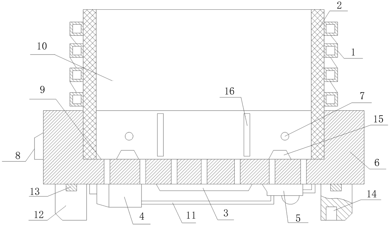
[0016] Such as figure 1 The high-efficiency heat dissipation device for an electric vehicle battery includes a heat exchange tube 1, a heat exchange plate 2, a thermoelectric power generation device 3, a semiconductor refrigeration device 4, a ventilation fan 5, a bearing base 6, a temperature sensor 7 and a control circuit 8, The upper end surface of the bearing base 2 is provided with a positioning groove 9 with a cross-section in the shape of "凵", a number of through holes 10 are evenly distributed on the lower end surface, and at least one heat exchange tube 1 is installed on the upper end surface of the bearing base 6, and the axis of the positioning groove 9 is in a spiral shape. structural distribution, and form a tubular structure heat exc...


PUM

PropertyMeasurementUnit
heightaaaaaaaaaa
heightaaaaaaaaaa

Abstract

The invention relates to a high-efficiency heat-dissipating device for a battery of an electric vehicle. The high-efficiency heat-dissipating device comprises a heat exchange tube, a heat exchange plate, a temperature-difference power generation device, semiconductor refrigerating devices, ventilating fans, a bearing base, temperature sensors and a control circuit, wherein a positioning groove isarranged on the upper end surface of the bearing base, and a plurality of through holes are uniformly distributed on the lower end surface of the bearing base; the heat exchange tubes are arranged onthe upper end surface of the bearing base and form a heat exchange cavity coaxially distributed with the positioning groove; the heat exchange plate is connected with the heat exchange tubes; the temperature-difference power generation device, the semiconductor refrigerating devices and the ventilating fans are respectively positioned on the lower end surface of the bearing base; the temperature sensors are uniformly distributed on the inner side surface of the positioning groove; the control circuit is embedded on the side surface of the bearing base. The high-efficiency heat-dissipating device has the beneficial effects that on the one hand, effective bearing and positioning can be effectively met for storage battery equipment for the electric vehicle, and on the other hand, the workingefficiency for heat-dissipating work of a storage battery can be greatly improved and recovery utilization ratio of heat energy can be effectively realized.

Description

technical field [0001] The invention relates to a cooling device, in particular to a high-efficiency cooling device for an electric vehicle battery. Background technique [0002] At present, the electric energy used by the tram vehicle equipment is provided by the battery. In actual use, it is found that the battery equipment of the electric vehicle is easy to generate a large amount of heat during operation. If the battery cannot be cooled in a timely and effective manner, It is very easy to seriously affect the performance of battery equipment, and even cause fires in severe cases, which seriously affects the operation performance and safety of electric vehicles. Although fans and other equipment can meet the needs of use, on the one hand, the cooling efficiency is poor and cannot effectively meet the needs of electric vehicles. The layout of the equipment room in the vehicle is complicated, which reduces the comprehensive use efficiency of the vehicle and increases the d...

Claims


Application Information

Patent Timeline
Patent Type & Authority Applications(China)
IPC IPC(8): H01M10/613H01M10/625H01M10/6554H01M10/6556H01M10/6563H01M10/6566H01M10/6572H01M2/10
CPCH01M2220/20H01M10/613H01M10/625H01M10/6554H01M10/6556H01M10/6563H01M10/6566H01M10/6572H01M50/20Y02E60/10
Inventor 陈春丽
Owner 陈春丽
Why Eureka
Try Eureka