
Angle-adjustable light supplementing lamp and angle regulation method

A technology of supplementary lighting and adjustment, which is applied in the direction of optics, lighting devices, instruments, etc., can solve the problems of troublesome angle adjustment, cumbersome installation, and easy falling off of the lampshade, so as to achieve the effect of easy installation and disassembly, and prevent accidental falling off

Pending Publication Date: 2018-11-27
方志祥
View PDF0 Cites 5 Cited by
  • Summary
  • Abstract
  • Description
  • Claims
  • Application Information

AI Technical Summary

Problems solved by technology

[0002] It is troublesome to adjust the angle of the existing camera equipment such as the fill light, and the fastening structure used to adjust the angle on both sides is too complicated; there is no locking part between the lampshade and the lamp body, and the lampshade is easy to fall off under the action of external force. Affects the fill light effect; the upper and lower covers and side panels of the lamp body are not installed from the outside, and the installation is too cumbersome and complicated

Method used


Image

  • Angle-adjustable light supplementing lamp and angle regulation method
  • Angle-adjustable light supplementing lamp and angle regulation method
  • Angle-adjustable light supplementing lamp and angle regulation method

Examples


Embodiment Construction

[0041] In order to fully understand the technical content of the present invention, the technical solutions of the present invention will be further introduced and illustrated below in conjunction with specific examples, but not limited thereto.

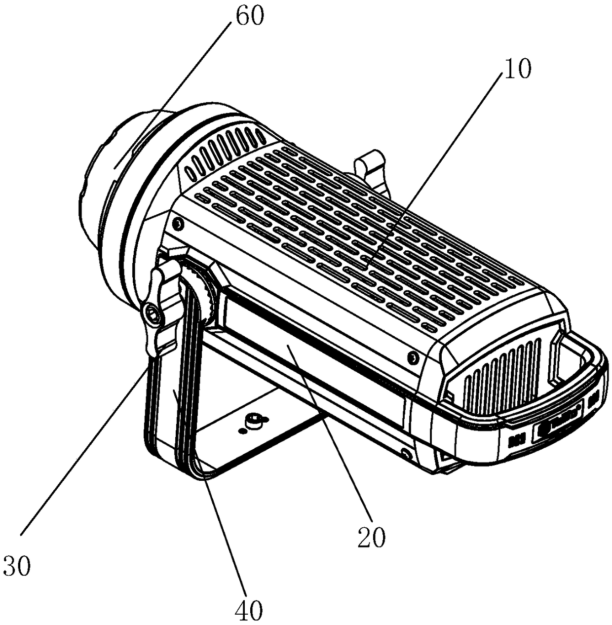
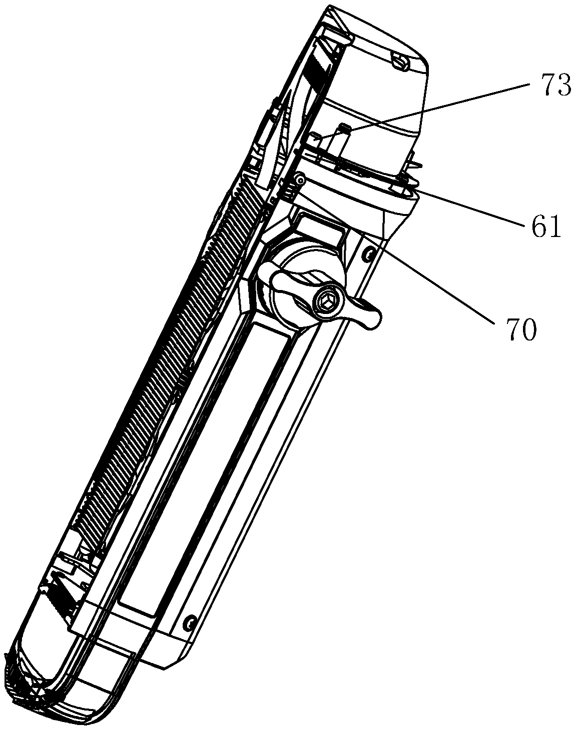
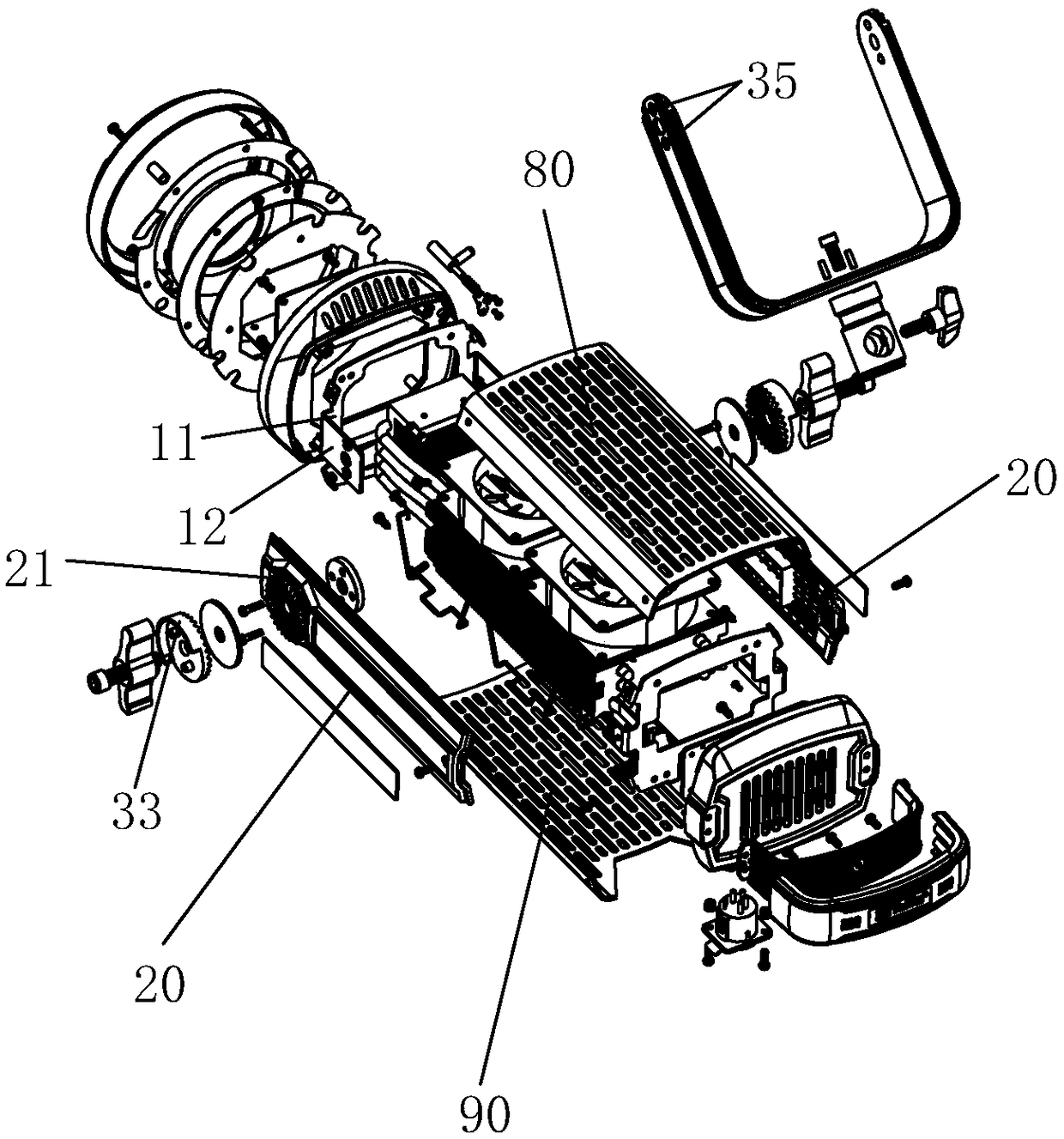
[0042] Such as Figure 1 to Figure 5 As shown, an angle-adjustable supplementary light includes a supplementary light body 10, a side plate 20 is provided on the side of the supplementary light body 10, and a rotating assembly 30 and a U-shaped bar 40 are included. The rotating assembly 30 and the side plate 20 Connect and adjust the rotating assembly 30 to connect and fix the U-shaped bar 40 and the side plate 20 . When the rotating assembly 30 is rotated outward, the U-shaped bar 40 can be separated from the side plate 20, and the angle between the U-shaped bar 40 and the side plate 20 can be adjusted, and the U-shaped bar 40 and the side plate 20 can be connected by tightening the rotating assembly 30 inwardly. The side panels 20...


PUM


Abstract

The invention provides an angle-adjustable light supplementing lamp and an angle regulation method. The angle adjustable light supplementing lamp comprises a light supplementing lamp body, wherein theside surface of the light supplementing lamp body is provided with a side plate; the angle-adjustable light supplementing lamp also comprises a rotating assembly and a U-shaped element; the rotatingassembly is connected with the side plate; the rotating assembly is regulated for fixedly connecting the U-shaped rod with the side plate. Through regulating the rotating assembly, the U-shaped rod and the side plate are connected and fixed; a mode of engaging and connecting a first engagement tooth on a connecting male element with a second engaging teeth arranged on the connecting mother elementis used for realizing the connection and fixation between the U-shaped rod and the side plate; a screw sequentially passes through the regulating knob, the U-shaped rod, a chain wheel and a connecting mother element and are connected with a threaded screw hole; the angle between the U-shaped rod and the side plate is regulated; the regulating knob is tightly screwed; the first engaging tooth andthe second engaging tooth are engaged, connected and fixed so as to connect and fix the U-shaped rod and the side plate. The telescopic assembly achieves the telescopic position clamping effect on a lamp shade, so that the accidental falling condition of the lamp shade is prevented.

Description

technical field [0001] The invention relates to a camera equipment, more specifically to an angle-adjustable supplementary light and an angle adjustment method. Background technique [0002] It is troublesome to adjust the angle of the existing camera equipment such as fill light, and the fastening structure on both sides of the adjustment angle is too complicated; the lampshade and the lamp body have no locking parts, and the lampshade is easy to fall off under the action of external force. Affects the fill light effect; the upper and lower covers and side panels of the lamp body are not installed from the outside, and the installation is too cumbersome and complicated. Contents of the invention [0003] The purpose of the present invention is to overcome the defects of the prior art, and provide an angle-adjustable supplementary light and an angle adjustment method. [0004] To achieve the above object, the present invention adopts the following technical solutions: ...

Claims


Application Information

Patent Timeline
IPC IPC(8): G03B15/03F21V21/30
CPCG03B15/03F21V21/30
Inventor 方志祥
Owner 方志祥
Learn More