Liquid tank leakage stopping device

A liquid tank and flange technology, applied in the field of liquid tank plugging devices, can solve the problems of low use stability, user inconvenience, poor use effect, etc., and achieves high use stability, improved use reliability, and strong use effect. Effect

Inactive Publication Date: 2018-11-06
贾乙
View PDF11 Cites 1 Cited by
  • Summary
  • Abstract
  • Description
  • Claims
  • Application Information

AI Technical Summary

Problems solved by technology

[0002] As we all know, the liquid tank plugging device is a device used to seal the leaks on the surface of the liquid storage tank to prevent the excessive loss of liquid in the tank from affecting related production, and it has been widely used in related fields; The existing plugging device for liquid tanks includes a shrinkage frame, an inner sleeve, an outer sleeve, a baffle plate, a first flange connection plate, a second flange connection plate, two groups of bolts and two groups of nuts. There is a working chamber, the right end of the shrink frame is provided with an opening, and the opening communicates with the working chamber, the first flange connection plate is installed on the right side wall of the shrink frame, the first flange connection plate and the second flange Two sets of first through holes and two sets of second through holes are respectively provided on the front side and the rear side of the connection plate, the outer side walls of the two sets of bolts and the inner side walls of the two sets of nuts are threaded structures, and the left end of the outer sleeve Connected with the left side wall of the working chamber, the left end of the inner sleeve is inserted into the right end of the inner sleeve, the baffle is installed on the right end of the inner sleeve, and a pull rod is arranged on the side wall of the inner sleeve, and the pull rod passes through Shrink frame; when using the existing plugging device for liquid tanks, two sets of bolts are passed through two sets of second through holes and two sets of first through holes, and two sets of nuts are screwed onto the two sets of bolts to fix the shrinkage frame. frame, and move the pull rod to drive the inner casing and drive the baffle to move to the leak to seal the leak; however, it is found that the existing liquid tank leak plugging device is inconvenient to use and cannot automatically seal the leak blockage, which brings inconvenience to users and has low practicability; moreover, its use stability is low and its use effect is poor, resulting in its low reliability in use

Method used


Image

  • Liquid tank leakage stopping device
  • Liquid tank leakage stopping device
  • Liquid tank leakage stopping device

Examples


Embodiment Construction

[0015] The specific implementation manners of the present invention will be further described in detail below in conjunction with the accompanying drawings and embodiments. The following examples are used to illustrate the present invention, but are not intended to limit the scope of the present invention.

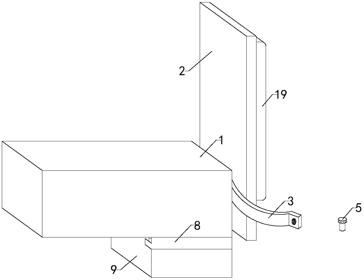
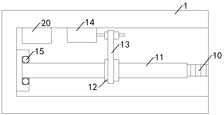
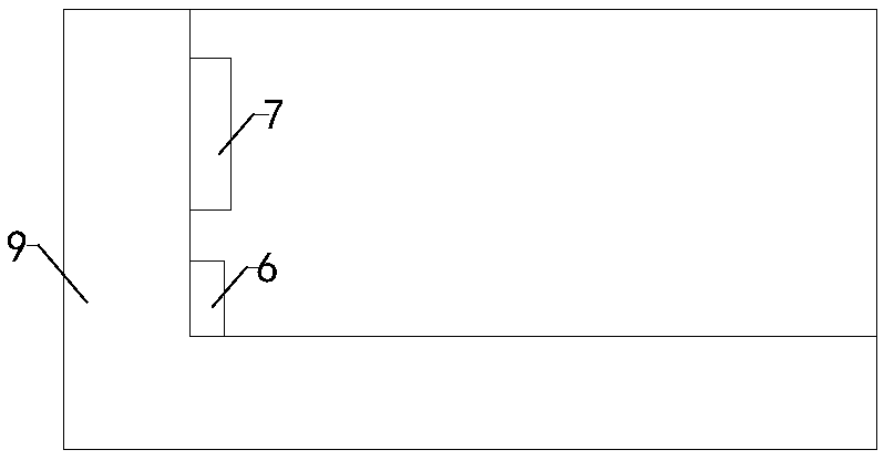
[0016] like Figure 1 to Figure 4 As shown, a liquid tank plugging device of the present invention includes a shrinkage frame 1, a baffle plate 2, a first flange connection plate 3, a second flange connection plate 4, two groups of bolts 5 and two groups of nuts, and the contraction frame There is a working chamber inside, the right end of the shrink frame is provided with an opening, and the opening communicates with the working chamber, the first flange connection plate is installed on the right side wall of the shrink frame, the first flange connection plate and the second flange connection plate Two groups of first through holes and two groups of second through holes ...


PUM


Abstract

The invention relates to the technical field of mechanical equipment accessory devices, in particular to a liquid tank leakage stopping device. The liquid tank leakage stopping device is relatively convenient to use, is capable of automatically blocking leakage holes to bring convenience to users, and is relatively high in practicability, relatively high in using stability and relatively strong inusing effect so as to improve the using reliability. The liquid tank leakage stopping device comprises a shrinkage frame, a baffle, a first flange connection disk, a second flange connection disk, two groups of bolts and two groups of nuts, wherein the shrinkage frame is internally provided with a working cavity; an opening is formed in the right end of the shrinkage frame; both the outer side walls of the two groups of bolts and the inner side walls of the two groups of nuts are of threaded structures; the liquid tank leakage stopping device furthermore comprises a liquid sensor, a sensor, two groups of limiting frames, a storage box, a threaded rod, a threaded pipe, a driving gear, a driven gear, a chain and a servo motor; the sensor is mounted in a placing groove and electrically connected with the liquid sensor; the chain is sleeved on the driving gear and the driven gear; the liquid tank leakage stopping device furthermore comprises a plurality of groups of sucking disks; and a plurality of groups of brackets are arranged on the right side wall of the first flange connection disk.

Description

technical field [0001] The invention relates to the technical field of accessory devices of mechanical equipment, in particular to a leak-stopping device for a liquid tank. Background technique [0002] As we all know, the liquid tank plugging device is a device used to seal the leaks on the surface of the liquid storage tank to prevent the excessive loss of liquid in the tank from affecting related production, and it has been widely used in related fields; The existing plugging device for liquid tanks includes a shrinkage frame, an inner sleeve, an outer sleeve, a baffle plate, a first flange connection plate, a second flange connection plate, two groups of bolts and two groups of nuts. There is a working chamber, the right end of the shrink frame is provided with an opening, and the opening communicates with the working chamber, the first flange connection plate is installed on the right side wall of the shrink frame, the first flange connection plate and the second flange...

Claims


Application Information

Patent Timeline
Patent Type & Authority Applications(China)
IPC IPC(8): B65D90/22
CPCB65D90/22
Inventor 贾乙
Owner 贾乙
Why Eureka
Try Eureka