Elevator landing floor hole filling system and method thereof

A technology for elevator landings and holes, which is used in elevators, lifts, transportation and packaging in buildings, can solve problems such as occupying a large space, and achieve the effect of protecting safety and ensuring effectiveness.

Inactive Publication Date: 2018-10-12
SHANGHAI SHENGDISI AUTOMATION EQUIP
View PDF5 Cites 1 Cited by
  • Summary
  • Abstract
  • Description
  • Claims
  • Application Information

AI Technical Summary

Problems solved by technology

[0003] Existing residential elevators need to be installed in the shaft of the building, and also need to be equipped with a dedicated elevator machine room, which takes up a lot of space

Method used


Image

  • Elevator landing floor hole filling system and method thereof
  • Elevator landing floor hole filling system and method thereof
  • Elevator landing floor hole filling system and method thereof

Examples


Embodiment 1

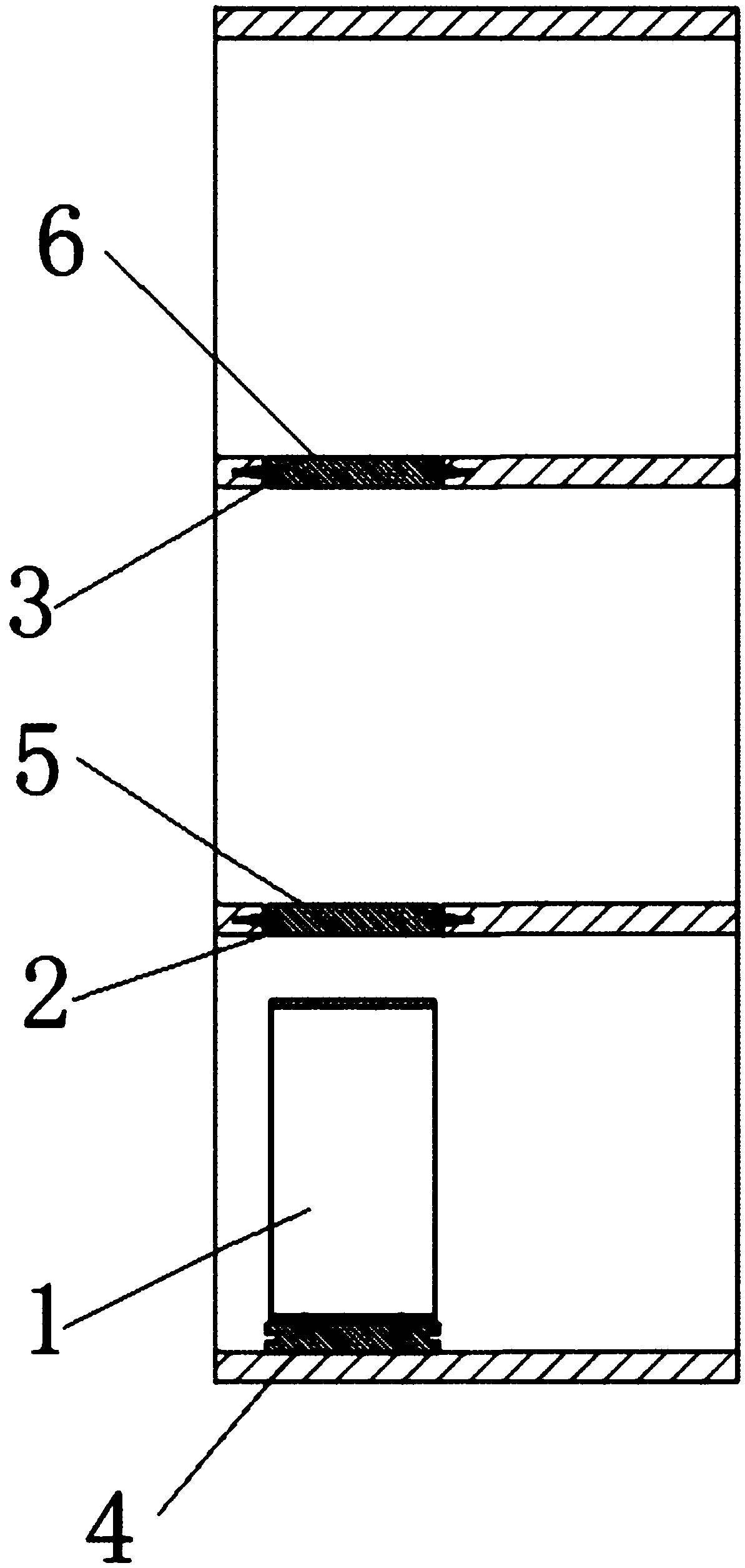
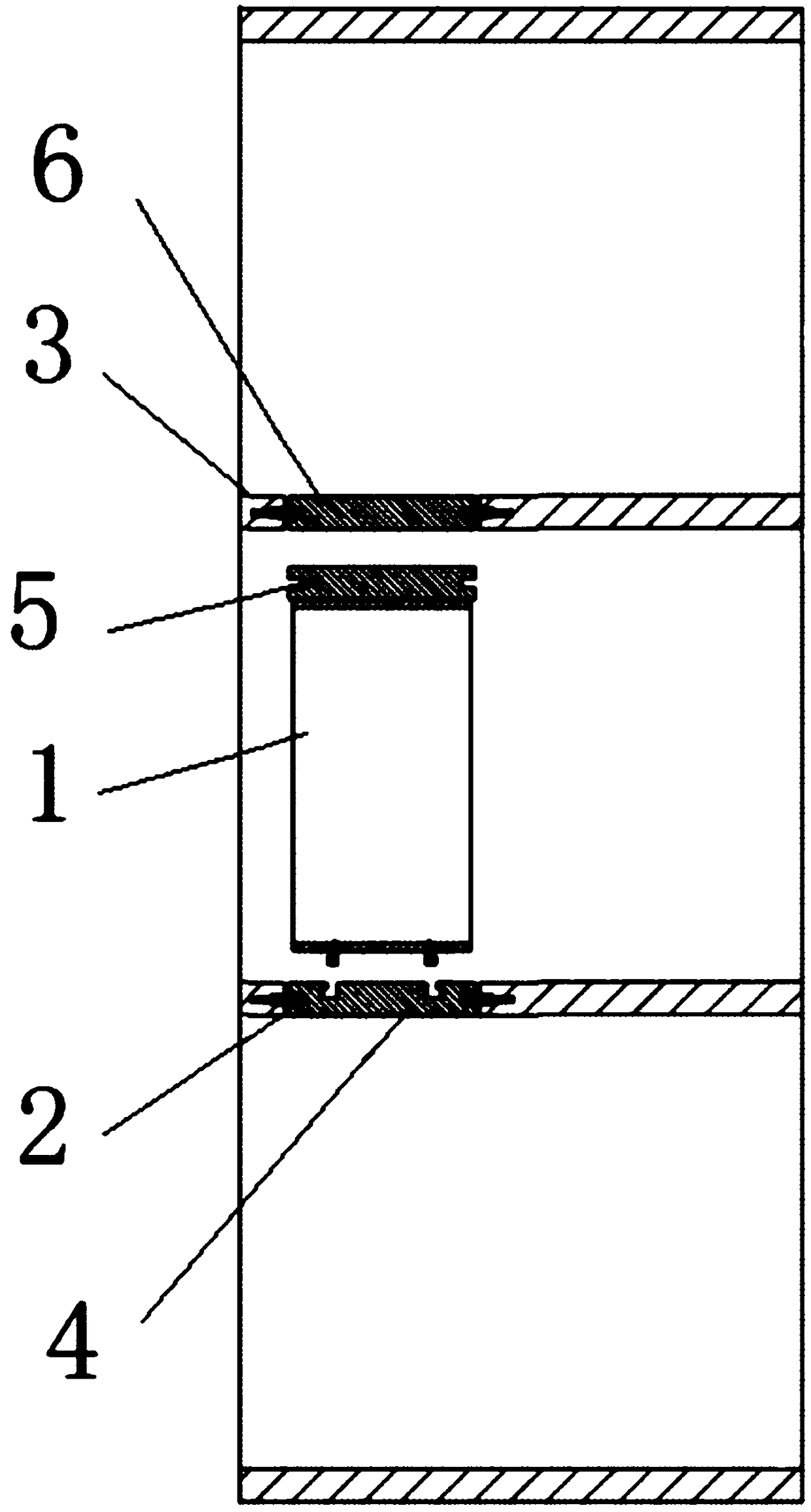
[0030] like Figure 1-5 As shown, the floor hole filling system of an elevator landing in this embodiment is used for a three-story elevator without a hoistway. The elevator includes an elevator control system, a car 1, a hole 2 on the second floor and a hole 3 on the third floor, and also includes a shape The car bottom cover plate 4, the second floor cover plate 5 and the third floor cover plate 6 matched with the hole 2 on the second floor and the hole 3 on the third floor, the bottom of the car 1 is connected with the car through the first normally closed electromagnetic opening and locking device 7. The bottom cover plate 4 is locked and fixed, the second floor hole 2 is locked and fixed with the second floor cover plate 5 through the second normally closed electromagnetic opening and locking device 8, and the third floor hole 3 is locked and fixed through the third normally closed electromagnetic opening and locking device 9 Locked and fixed with the cover plate 6 on the...

Embodiment 2

[0042] The difference between this embodiment and Embodiment 1 is that the elevator is an elevator with a shaft, the first normally closed electromagnetic opening and locking device is arranged on the car floor cover 4, and the second normally closed electromagnetic opening and locking device is arranged on On the cover plate 5 of the second floor, the third normally closed electromagnetic opening and locking device is arranged on the cover plate 6 of the third floor.

[0043] A method according to the above-mentioned elevator floor hole filling system:

[0044] When the elevator was on the first floor, the elevator control system controlled the first normally closed electromagnetic unlocking and locking device 7, the second normally closed electromagnetic unlocking and locking device 8 and the third normally closed electromagnetic unlocking and locking device 9, so that The car bottom cover plate 4 is locked and fixed on the bottom of the car 1, the second floor cover plate 5...


PUM


Abstract

The invention provides an elevator landing floor hole filling system and method thereof for an elevator for at most three floors. The elevator comprises an elevator control system, a car, a second-floor hole and a third-floor hole. The elevator is characterized by further comprising a car bottom cover plate, a second-floor cover plate and a third-floor cover plate cooperating with the second-floorhole and the third-floor hole in appearance; the car bottom cover plate is locked and fixed through a first normally closed electromagnetic opening and locking device at the bottom of the car; the second-floor cover plate is locked through a second normally closed electromagnetic opening and locking device in the second-floor hole; the third-floor cover plate is locked and fixed through a third normally closed electromagnetic opening and locking device in the third-floor hole; and the elevator control system is in electric control connection with the first normally closed electromagnetic opening and locking device, the second normally closed electromagnetic opening and locking device and the third normally closed electromagnetic opening and locking device. After the car leaves from a landing, the floor holes in the car projection area are effectively filled, so that the danger of persons falling from the floor holes is prevented, and the safety of surrounding persons is protected.

Description

[0001] This application takes the Chinese invention patent with application date of August 17, 2017 and application number CN201710707914.5 as the basis for claiming priority. technical field [0002] The invention relates to the technical field of elevator machinery, in particular to a system and method for filling holes in floor slabs of elevator landings. Background technique [0003] Existing residential elevators all need to be installed in the shaft of the building, and also need to be equipped with a dedicated elevator machine room, which takes up a lot of space. With the improvement of living standards and the problem of population aging, more and more residents with housing conditions of two floors or above have demand for their own home elevators. Therefore, hoistway-less elevators have occurred on the market. [0004] When the hoistway-less elevator travels between floors, the top needs to ensure that it will not touch foreign objects to ensure safety. At the sa...

Claims


Application Information

Patent Timeline
Patent Type & Authority Applications(China)
IPC IPC(8): B66B11/02B66B5/00
CPCB66B5/00B66B11/0226
Inventor 樊利平鲁苍袁忠才
Owner SHANGHAI SHENGDISI AUTOMATION EQUIP
Why Eureka
Try Eureka