
Electronic equipment bracket with storage box

A technology for electronic equipment and storage boxes, applied in mechanical equipment, machine/stand, supporting machine, etc., can solve the problem of inconvenient use of the stand, and achieve the effect of good connection effect, convenient use and tight connection

Inactive Publication Date: 2018-08-24
ZHENGZHOU QISHUO ELECTRONICS TECH CO LTD
View PDF0 Cites 0 Cited by
  • Summary
  • Abstract
  • Description
  • Claims
  • Application Information

AI Technical Summary

Problems solved by technology

[0004] The object of the present invention is to solve the problem of inconvenient use of the above-mentioned electronic equipment support, and the present invention provides an electronic equipment support with a storage box. A garbage chute is arranged at the bottom of the support, and the garbage that users eat snacks when watching movies Just place it directly in the garbage chute, the device is simple and easy to use

Method used


Image

  • Electronic equipment bracket with storage box
  • Electronic equipment bracket with storage box
  • Electronic equipment bracket with storage box

Examples


Embodiment 1

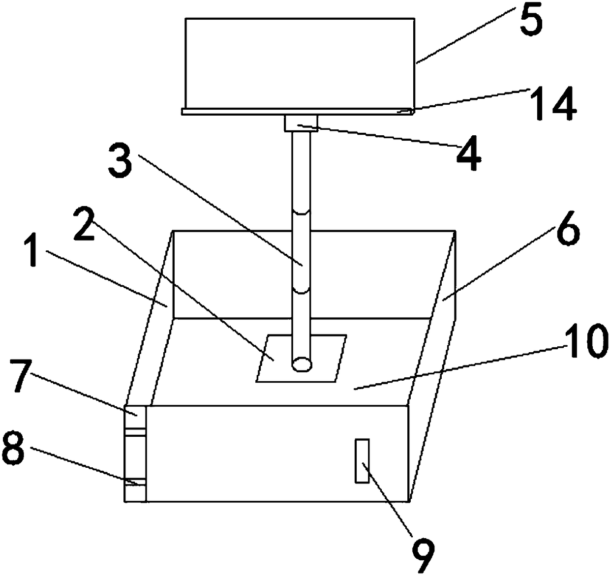
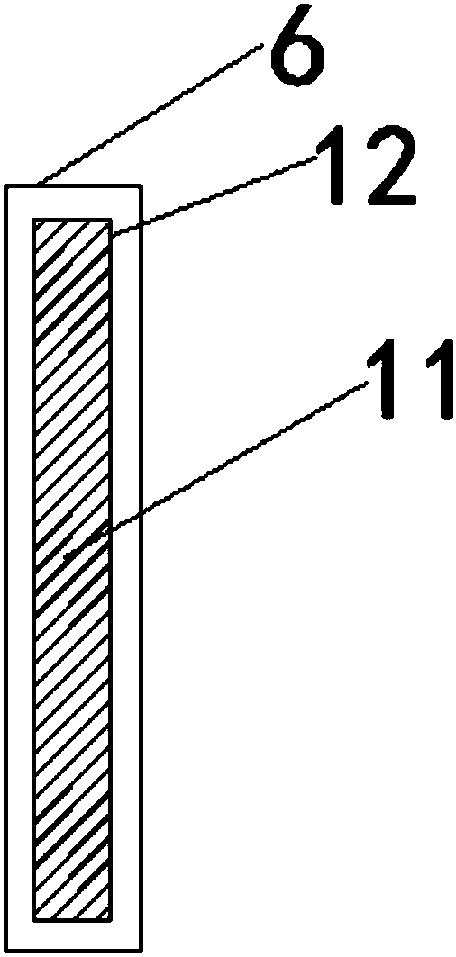
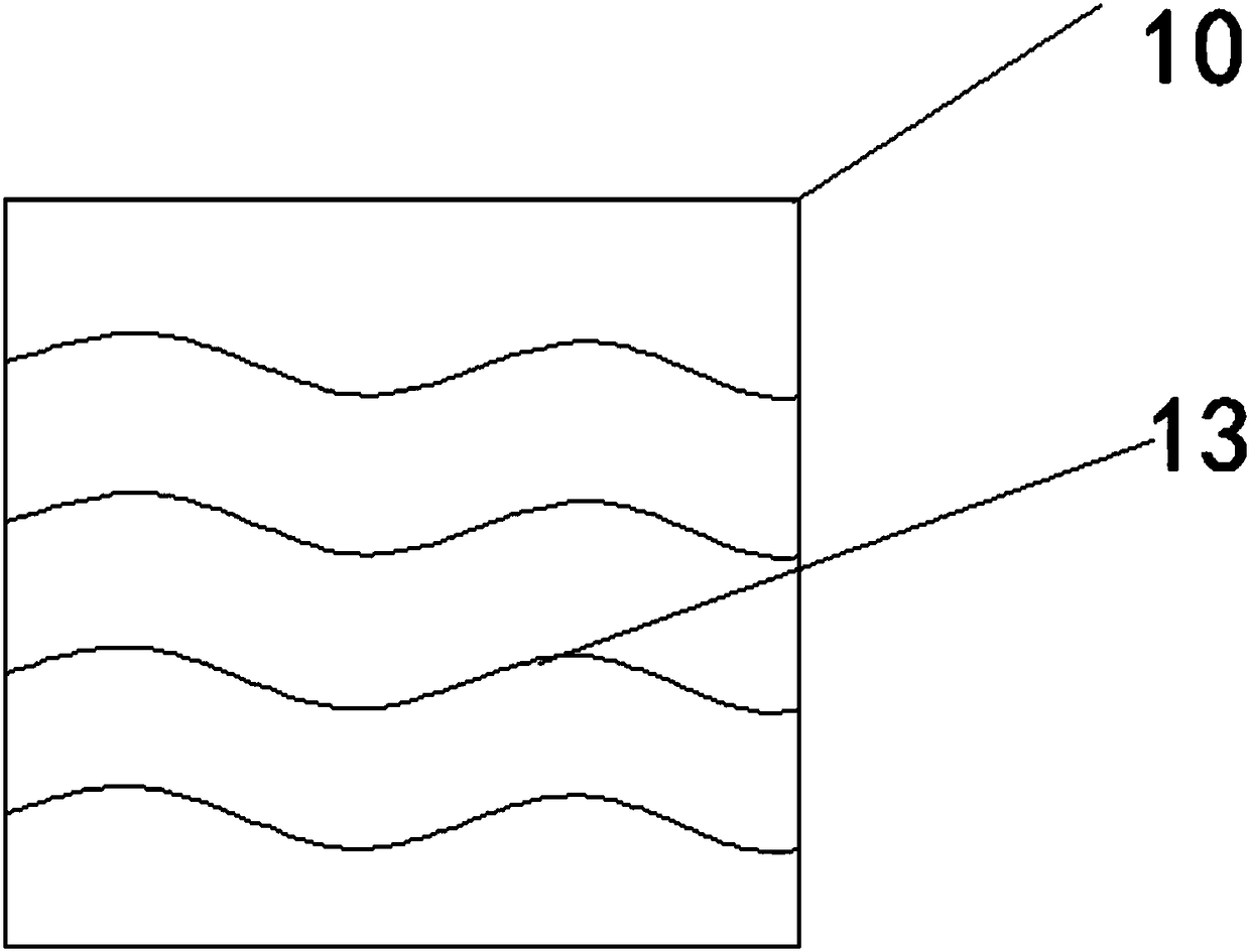
[0026] refer to Figure 1-3 , an electronic device bracket with a storage box, comprising a base 2, a support pole 3 is arranged on the base 2, a placement plate 5 for placing electronic equipment is arranged on the support pole 3, the placement plate 5 is a tank structure, and the base 2 is provided with There is a garbage chute 1, the garbage chute 1 includes a base plate 10 fixed on the base 2, vertical plates 6 are arranged around the base plate 10, at least one side of the base plate 10 is provided with a hinged seat 8, or any two adjacent Any vertical plate 6 between the vertical plates 6 is provided with hinged seat 8, and hinged seat 8 is provided with hinged shaft 7, and the vertical plate 6 near hinged shaft 7 is connected with hinged shaft 7, and the vertical plate connected on the hinged shaft 7 6 is provided with a pull ring 9 for pulling the vertical plate 6 .

[0027] Working principle: When a user uses a mobile phone to watch a movie, the user places the brack...

Embodiment 2

[0029] Based on Example 1, with reference to Figure 1-3 , the end of the pole 3 of this embodiment away from the base 2 is provided with a swivel head 4 for adjusting the viewing angle, the swivel head 4 can rotate in all directions, and the placement plate 5 is arranged on the swivel head 4.

[0030] By setting the swivel head 4 on the support rod 3, it is convenient to adjust the best viewing angle for watching movies, and the rotation of the swivel head 4 can drive the placement plate 5 arranged on the swivel head 4 to rotate, and then drive the electronic equipment in the placement plate 5 to rotate , you can adjust to the best viewing angle.

Embodiment 3

[0032] Based on Example 1, with reference to Figure 1-3 , the pole 3 of this embodiment is a liftable mechanism.

[0033] The support rod 3 is set in a liftable form, and the height of the placement plate 5 can be adjusted through the support rod 3, so as to avoid stuffing other things on the base 2 to raise the height when the height needs to be adjusted, or to watch movies when the support rod 3 is too high It is also inconvenient.


PUM


Abstract

The invention discloses an electronic equipment bracket with a storage box. The electronic equipment bracket with the storage box comprises a base; the base is provided with a support rod; the supportrod is provided with a placing plate for placing electronic equipment; the placing plate is of a groove body structure; a garbage groove is formed in a ground base, and comprises a base plate fixed on the base; vertical plates are arranged perpendicular to the periphery of the base plate; a hinge base is arranged on at least one edge of the base plate, or a hinge base is arranged on any verticalplate of any two adjacent vertical plates; a hinge shaft is arranged on the hinge base; the vertical plate near the hinge shaft is connected with the hinge shaft; and the vertical plate connected to the hinge shaft is provided with a pull ring for pulling the vertical plate. Users can watch films during eating snacks; finished snack garbage is directly placed in the garbage groove formed in the bracket base; and after the garbage groove is fully filled with the garbage, the hinged vertical plate is pulled away, so that the garbage in the garbage groove can be all thrown, and the garbage grooveis cleaned more conveniently.

Description

technical field [0001] The invention relates to the technical field of electronic equipment, in particular to an electronic equipment bracket with a storage box. Background technique [0002] With the development of modern technology, the development of electronic equipment products tends to be miniaturized, thinned and portable. Taking the mobile phone as an example, the mobility and portability of the mobile phone are very good, but the mobile phone still has some unfavorable factors. When using the mobile phone, it needs to be held in order to obtain a better viewing angle, although the weight of the current mobile phone is continuously reduced. , but no matter how light it is, long-term hand-holding will cause fatigue, so a stand is set up to place it. [0003] The existing electronic device brackets only play a supporting role, but most people like to eat snacks when watching movies with their mobile phones, and most of them watch movies on the sofa or bed, so there is...

Claims


Application Information

Patent Timeline
Patent Type & Authority Applications(China)
IPC IPC(8): F16M11/08F16M11/28F16M11/16
CPCF16M11/08F16M11/16F16M11/28
Inventor 高翔
Owner ZHENGZHOU QISHUO ELECTRONICS TECH CO LTD
Learn More