Method for determining corrected rotational speed signal and electric motor device

A speed signal and motor technology, applied to devices using electric/magnetic methods, using electric/magnetic devices to transmit sensing components, measuring devices, etc., can solve problems such as hindering precise adjustment of motors

Active Publication Date: 2020-09-11
SCHAEFFLER TECH AG & CO KG
View PDF10 Cites 0 Cited by
  • Summary
  • Abstract
  • Description
  • Claims
  • Application Information

AI Technical Summary

Problems solved by technology

However, the angle signal and thus also the speed signal can have disturbances that prevent precise regulation of the electric motor

Method used


Image

  • Method for determining corrected rotational speed signal and electric motor device
  • Method for determining corrected rotational speed signal and electric motor device
  • Method for determining corrected rotational speed signal and electric motor device

Examples


Embodiment Construction

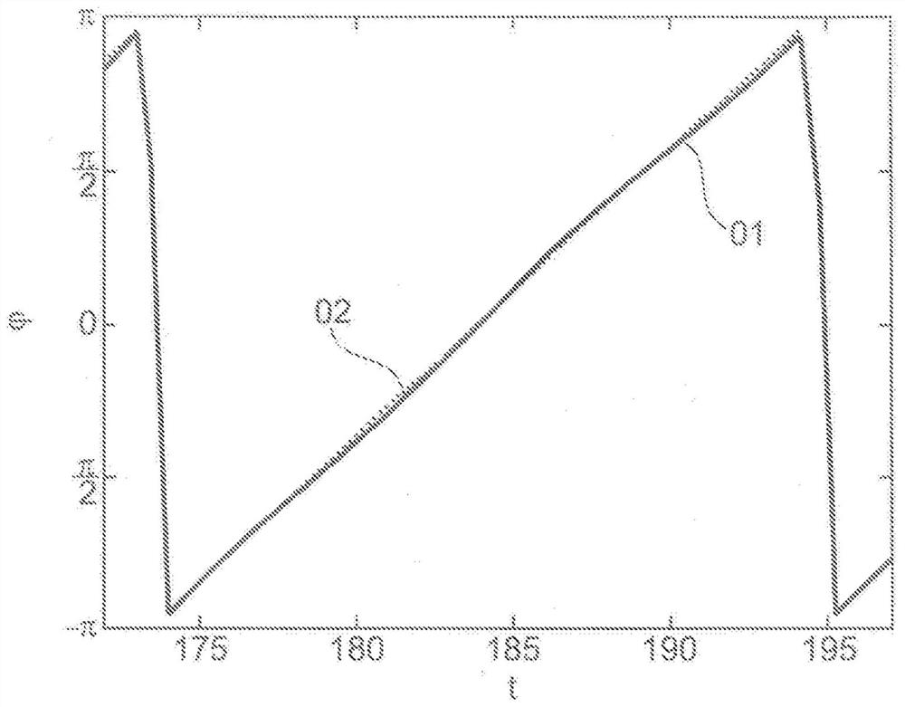
[0055] figure 1 The course of the rotational angle signal 01 output by the commutation sensor is shown, which shows the magnetic field angle as a function of time and is represented as a solid line. Correspondingly, the ideal rotational angle signal 02 is shown as a dashed line. In each revolution from -π to +π, the rotational angle signal 01 wipes out a complete cycle. A comparison between the ideal rotation angle signal 02 and the measured rotation angle signal 01 shows that the commutation sensor receives a small rotation angle error 03 (at figure 2 shown in ), which oscillates around the ideal rotational angle signal 02 similarly to a sinusoidal interference signal on the rotational angle signal 01 .

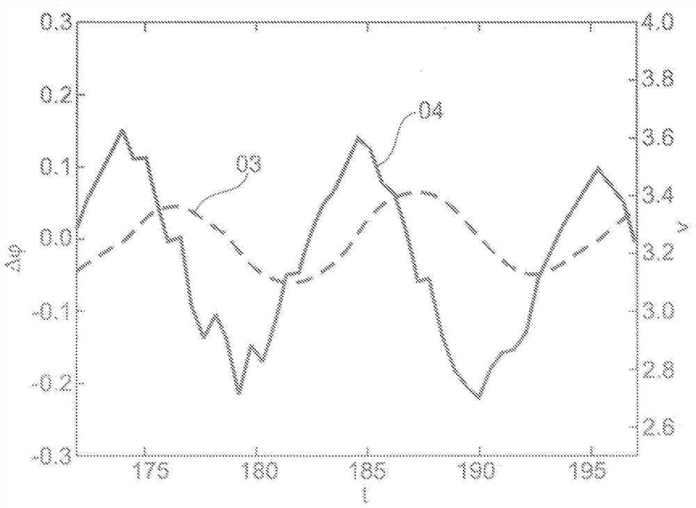
[0056] figure 2 The rotational angle error 03 is shown as a function of time as a magnetic field angle difference. Furthermore, raw rotational speed signal 04 is shown, which is obtained according to the invention by differentiating rotational angle signal 01 . It can...


PUM


Abstract

The invention relates to a method and an electric motor arrangement for determining a corrected rotational speed signal. In one step of the method, a periodic rotational angle signal is detected which has a periodic rotational angle error which is dependent on the rotational angle. Converting the rotation angle signal into a digital original speed signal (16), due to the rotation angle error, the digital original speed signal has an interference ripple, and the cycle duration of the interference ripple corresponds to the cycle duration of the rotation angle error . The digital raw rotational speed signal (16) comprises a plurality of sampled values ​​(07), which are spaced apart in time by the duration of the sampling period, the half-period duration of the disturbance ripple of the raw rotational speed signal (16) being determined. Averaging at least one pair of sampling values ​​(07) of the original rotational speed signal (16), the time interval of the at least one pair of sampling values ​​aside from the time discretization error is the interference ripple of the original rotational speed signal (16) The known half-cycle duration. The average value is obtained by averaging. A correction value is formed that is dependent on the sampling period duration and the frequency of the disturbance ripple to account for discretization errors. The corrected rotational speed signal is formed from the difference between the mean value and the corrected value. The correction signal varies in a sawtooth fashion as a function of the difference between the sampling period duration and the period duration of the disturbance ripple, the maximum amplitude of the correction signal also increasing with increasing frequency of the disturbance ripple.

Description

technical field [0001] The invention firstly relates to a method for determining a corrected rotational speed signal. The method is especially suitable for accurately determining the rotational speed of rotary electric machines. The invention also relates to an electric motor arrangement in which the method according to the invention is used. Background technique [0002] However, an exact speed signal is especially required in electric motors for drives, which are regulated more accurately than with conventional block commutation. The speed signal can be known via the angle signal, which can be detected with a commutation sensor. However, the angle signal and thus also the speed signal can have disturbances which prevent precise regulation of the electric motor. Solutions are known in the prior art with which these disturbances are to be corrected by correction values ​​known in advance. [0003] DE 102 60 862 A1 shows a method for correcting a sensor device for measuri...

Claims


Application Information

Patent Timeline
Patent Type & Authority Patents(China)
IPC IPC(8): G01P21/02G01P3/44G01D5/244
CPCG01P3/44G01P21/02G01D5/145G01D5/24476G01D5/2448G01P3/48
Inventor 本雅明·考夫纳
Owner SCHAEFFLER TECH AG & CO KG
Why Eureka
Try Eureka