Turnable power head for drilling box and drilling machine

A drilling rig power head and power head technology, which is applied in the field of power heads, can solve the problems of broken anchor rods in the drill hole and low work efficiency, so as to achieve accurate hole finding and avoid inaccurate hole finding

Pending Publication Date: 2018-05-04
ZOUCHENG TIANHE SCI & TECH
View PDF4 Cites 0 Cited by
  • Summary
  • Abstract
  • Description
  • Claims
  • Application Information

AI Technical Summary

Problems solved by technology

[0002] When excavating underground in existing coal mines, it is necessary to move forward while digging, and then support the tunnel. Due to the limited space in the tunnel, excavation and support operations tend to conflict with each other. To resolve this conflict, people use airborne hydraulic bolts Drilling rigs are used to carry out tunnel support while excavating and moving forward. However, due to the limited space in the underground of coal mines, the anchor rods used underground are relatively long. Install the anchor rod in the drill hole, and then move the drilling rig back to the original position to clamp the anchor rod, so that the anchor rod continues to drill a certain distance inward to fix the anchor rod in the drill hole. Since the drill rod and the anchor rod are thin, The diameter of the hole drilled by the drill pipe is small. Once there is a slight deviation between the anchor rod, the drill hole and the power head, the anchor rod may break in the drill hole, and the work efficiency is low

Method used


Image

  • Turnable power head for drilling box and drilling machine
  • Turnable power head for drilling box and drilling machine
  • Turnable power head for drilling box and drilling machine

Examples


Embodiment Construction

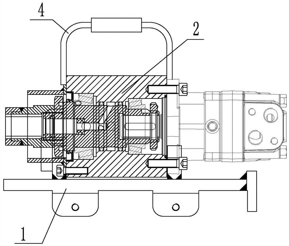
[0008] A reversible drill box drill power head, such as figure 1 , figure 2 and image 3 As shown, it includes the fixed seat 1 and the power head 2, the hinged seats 3 are respectively installed on both sides of the upper part of the fixed seat 1, and the two sides of the lower part of the power head 2 are respectively provided with mounting seats 18, and the pin holes 19 are provided on the mounting seats 18, and the pin holes 19 are fitted with The hinged shaft 5 is installed, and the hinged shaft 5 is fitted in the hinged seat 3. After one hinged shaft 5 is extracted from the hinged seat 3 and the pin hole 19, the power head 2 can rotate around the other hinged shaft 5. The fixed seat 1 is installed on the airborne hydraulic rock bolter. With this structure, after the drill rod is removed, one hinged shaft 5 can be pulled out from the hinged seat 3 and the pin hole 19, and the power head 2 can be rotated around the other hinged shaft 5 to leave the original position, an...


PUM


Abstract

The invention relates to a turnable power head for a drilling box and a drilling machine. The turnable power head comprises a fixing base and a power head body, hinge bases are arranged at the two sides of the upper portion of the fixing base respectively, and mounting bases are arranged at the two sides of the lower portion of the power head body respectively; pin holes are formed in the mountingbases, hinge shafts are matched with the interiors of the pin holes and the hinge bases, and after one hinge shaft is drawn out from the corresponding hinge base and the corresponding pin hole, the power head body can rotate around the other hinge shaft. The turnable power head for the drilling box and the drilling machine has the advantages that after a drilling rod is disassembled, one hinge shaft can be drawn out from the corresponding hinge base and the corresponding pin hole, the power head body rotates around the other hinge shaft and leaves from the original position, then an anchor rod is arranged in a drilling hole, the power head body is rotated to the original position, and the anchor rod is clamped; then the drawn-out hinge shaft is inserted in the corresponding hinge base andthe corresponding pin hole again, the power head body is fixed to the original position, accordingly the anchor rod is aligned with the power head body and the drilling hole of which the drilling roddrills out, accurate hole finding is achieved, and the situation is avoided that the anchor rod is broken due to inaccurate hole finding of the anchor rod.

Description

technical field [0001] The invention relates to a power head, in particular to a reversible drilling machine power head. Background technique [0002] When excavating underground in existing coal mines, it is necessary to move forward while digging, and then support the tunnel. Due to the limited space in the tunnel, excavation and support operations tend to conflict with each other. To resolve this conflict, people use airborne hydraulic bolts Drilling rigs are used to carry out tunnel support while excavating and moving forward. However, due to the limited space in the underground of coal mines, the anchor rods used underground are relatively long. Install the anchor rod in the drill hole, and then move the drilling rig back to the original position to clamp the anchor rod, so that the anchor rod continues to drill a certain distance inward to fix the anchor rod in the drill hole. Since the drill rod and the anchor rod are thin, The diameter of the drilled hole drilled by...

Claims


Application Information

Patent Timeline
Patent Type & Authority Applications(China)
IPC IPC(8): E21B3/02E21D20/00
CPCE21B3/02E21D20/003
Inventor 田胜利闫丽岳宁张成张恩瑞
Owner ZOUCHENG TIANHE SCI & TECH
Why Eureka
Try Eureka