A control method for a valve base control system

A technology of valve base control and control method, applied in the direction of power transmission and AC network, etc., can solve the problem of low stability of valve base control method, and achieve the effect of solving low stability

Active Publication Date: 2020-06-02
GLOBAL ENERGY INTERCONNECTION RES INST CO LTD
View PDF9 Cites 0 Cited by
  • Summary
  • Abstract
  • Description
  • Claims
  • Application Information

AI Technical Summary

Problems solved by technology

[0004] Therefore, the technical problem to be solved by the present invention lies in the low stability of the existing valve base control mode.

Method used


Image

  • A control method for a valve base control system
  • A control method for a valve base control system

Examples


Embodiment Construction

[0037] The technical solutions of the present invention will be clearly and completely described below in conjunction with the accompanying drawings. Apparently, the described embodiments are some of the embodiments of the present invention, but not all of them. Based on the embodiments of the present invention, all other embodiments obtained by persons of ordinary skill in the art without making creative efforts belong to the protection scope of the present invention.

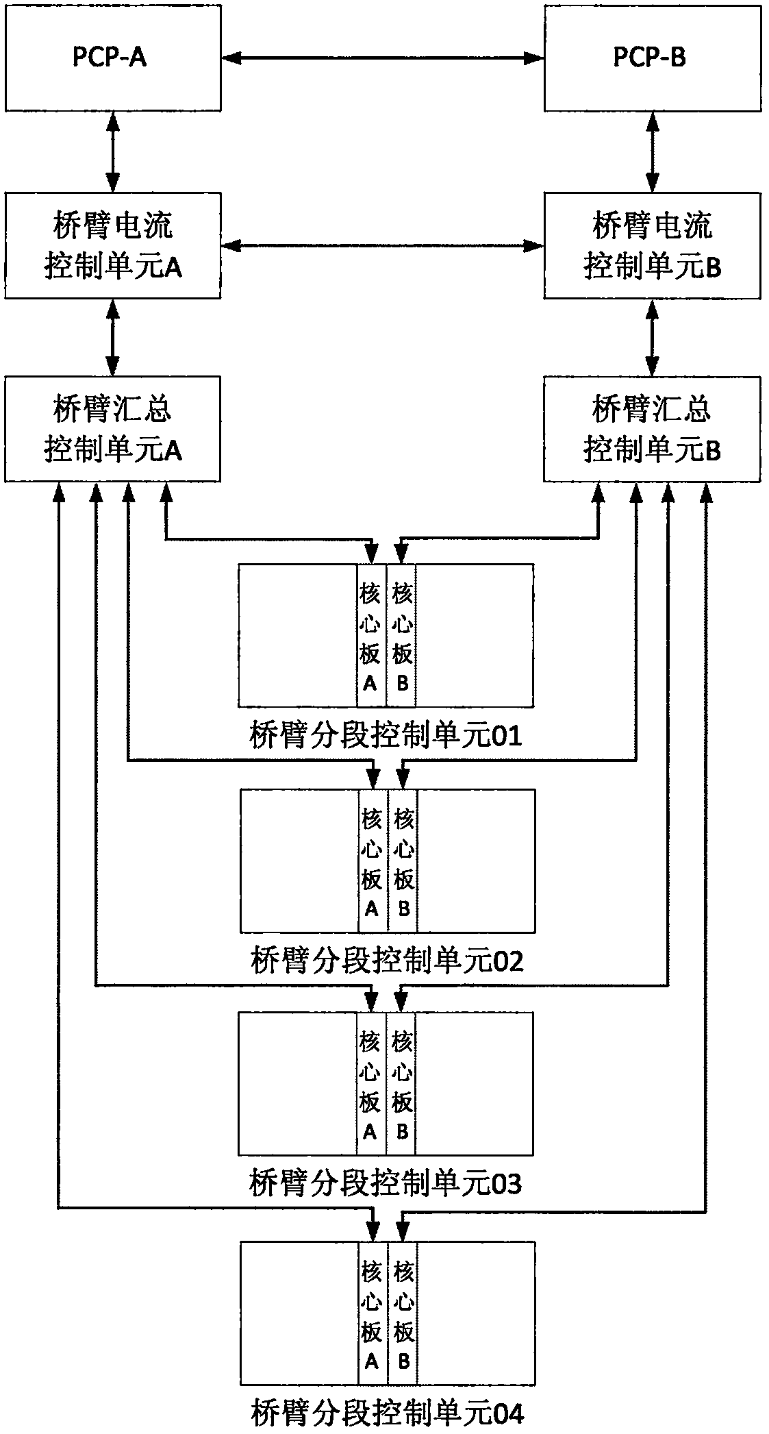
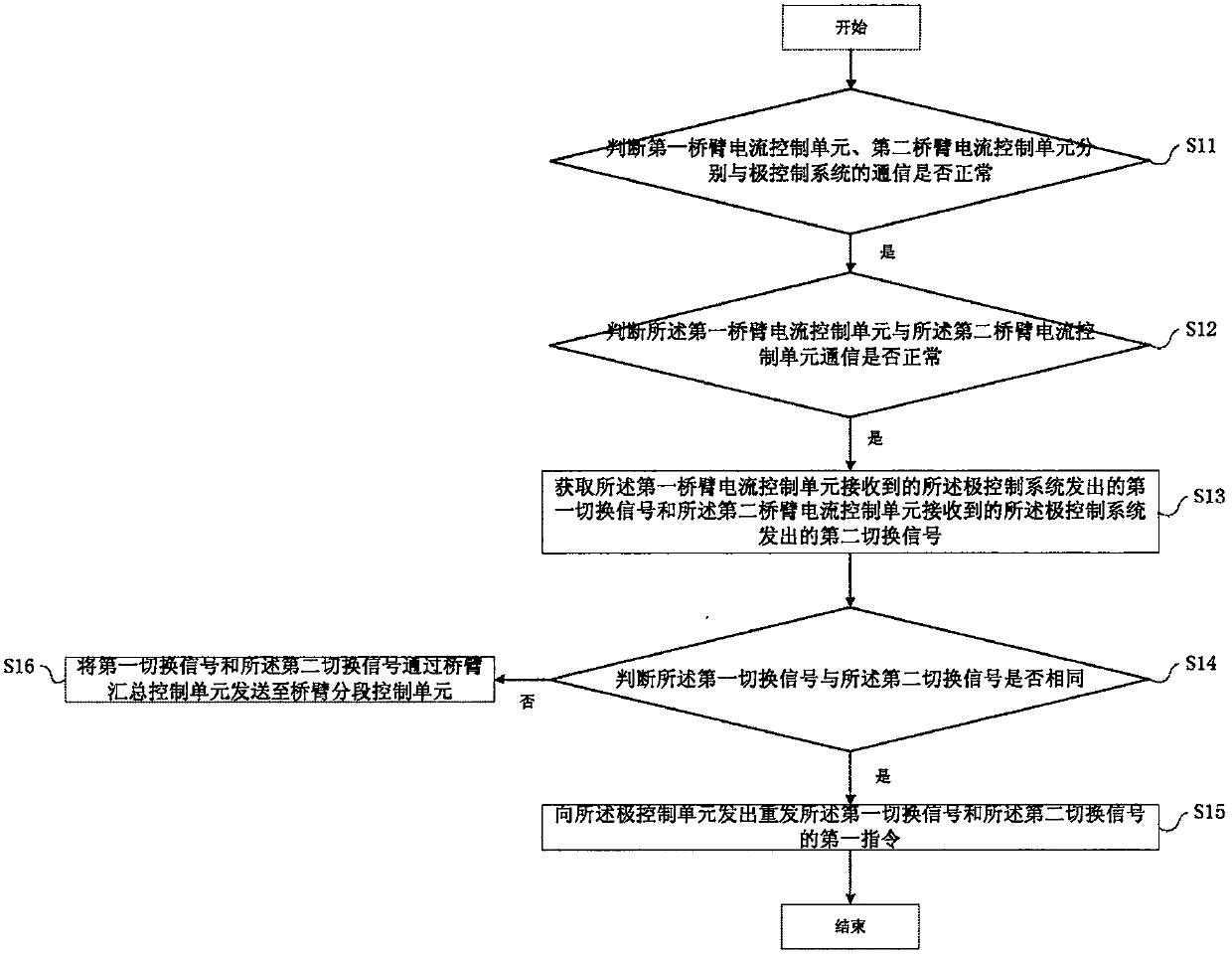
[0038] An embodiment of the present invention provides a control method for a valve base control system, which is applied to a valve base control system with dual redundant bridge arm control units, such as figure 2 shown, including:

[0039] S11, judging whether the communication between the first bridge arm current control unit and the second bridge arm current control unit and the pole control system is normal, when the communication between the first bridge arm current control unit and the pole control sy...


PUM


Abstract

The invention relates to a control method of a valve-based control system. The control method comprises: whether a first bridge arm current control unit and a second bridge arm current control unit carry out communication with a pole control system normally is determined; when both the first bridge arm current control unit and second bridge arm current control unit carry out communication with thepole control system normally, whether the first bridge arm current control unit and the second bridge arm current control unit carry out communication normally is determined; if so, a first switchingsignal that is sent by the pole control system and is received by the first bridge arm current control unit and a second switching signal that is sent by the polar control system and is received by the second bridge arm current control unit are obtained; whether first switching signal and the second switching signal are identical is determined; and if so, a first instruction for transmitting thefirst switching signal and the second switching signal again is sent to the pole control unit.

Description

technical field [0001] The invention relates to the technical field of flexible direct current transmission, in particular to a control method for a valve-based control system. Background technique [0002] As a new generation of DC transmission technology, flexible DC transmission has the advantages of high controllability and good flexibility, and has significant technical advantages in the integration of renewable energy, power supply in large cities, and the construction of future DC grids. The valve-based control system (VBC) is the intermediate link of the flexible HVDC control system. In terms of function, VBC is the intermediate hub connecting the upper pole control system (PCP) and the lower switching device controller (SMC). The core equipment of the diverter valve. Therefore, the stable and reliable operation of the valve-based control system plays a vital role in the entire flexible DC transmission system; [0003] In order to improve the stability and reliabi...

Claims


Application Information

Patent Timeline
Patent Type & Authority Patents(China)
IPC IPC(8): H02J3/36
CPCY02E60/60
Inventor 唐茹彬路建良关兆亮李霄梁伟
Owner GLOBAL ENERGY INTERCONNECTION RES INST CO LTD
Why Eureka
Try Eureka