
Automatic plate clamping device

A clamping device and plate technology, applied in the direction of transportation and packaging, conveyor objects, etc., can solve the problems of construction personnel's inconvenience, construction personnel's damage, and no fixation, so as to improve the quality of work and reduce redundant manual processes.

Inactive Publication Date: 2018-01-19
陕西通时迪力信息技术有限公司
View PDF0 Cites 0 Cited by
  • Summary
  • Abstract
  • Description
  • Claims
  • Application Information

AI Technical Summary

Problems solved by technology

[0002] At present, during the installation of wall panels, because the wall panels are too large, a large number of construction workers are required to carry them, which is extremely inconvenient and too heavy, which will endanger the personal safety of the construction workers and cause great inconvenience to the construction workers. The most important thing is that it is not fixed during installation, which is likely to cause damage to the construction personnel, and there is a lack of equipment developed for the transportation and installation of wall panels

Method used


Image

  • Automatic plate clamping device
  • Automatic plate clamping device

Examples


Embodiment Construction

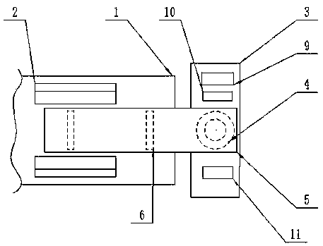
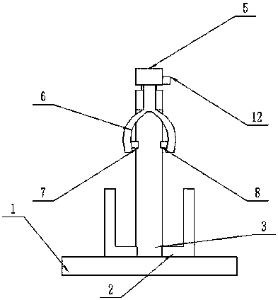
[0013] The present invention is specifically described below in conjunction with accompanying drawing, as Figure 1-2 As shown, an automatic plate clamping device includes a sliding belt (1), and a set of opposite L-shaped plate fixing frames (2) are arranged on the sliding belt (1), and the L-shaped plate fixing frame (2) An intelligent grabbing mechanism is provided above, and the intelligent grabbing mechanism consists of a frame (3), a rotating motor (4) arranged on the upper end of the frame (3), and a swinging mechanism fixed at the rotating end of the rotating motor (4). arm (5), a group of mechanical tightening arms (6) arranged on the lower surface of the swing arm (5), and infrared receivers (7) and infrared generators ( 8) Composition, the frame (3) is provided with a controller (9), mains interface (10) and capacitive touch screen (11), the controller (9) and mains interface (10), capacitive touch screen (11) is electrically connected with the intelligent grasping...


PUM


Abstract

The invention discloses an automatic plate clamping device. The automatic plate clamping device comprises a sliding belt. A set of opposite L-shaped plate fixing frames are arranged on the sliding belt. An intelligent grabbing mechanism is arranged above the L-shaped plate fixing frames and composed of a machine frame, a rotary motor arranged at the upper end of the machine frame, a swing arm of which one end is fixed to the rotary end of the rotary motor, a set of mechanical clamping arms arranged on the lower surface of the swing arm, an infrared receiver and an infrared generator, wherein the infrared receiver and the infrared generator are arranged on the two inner sides of one of the mechanical clamping arms correspondingly. The machine frame is provided with a controller, an electricsupply interface and a capacitive touch screen. The controller is electrically connected with the electric supply interface, the capacitive touch screen and the intelligent grabbing mechanism. The automatic plate clamping device has the beneficial effects of being simple in structure and high in practicability.

Description

technical field [0001] The invention relates to the field of plate equipment, in particular to an automatic plate clamping device. Background technique [0002] At present, during the installation of wall panels, because the wall panels are too large, a large number of construction workers are required to carry them, which is extremely inconvenient and too heavy, which will endanger the personal safety of the construction workers and cause great inconvenience to the construction workers. The most important thing is that it is not fixed during installation, which is likely to cause damage to the construction personnel, and there is a lack of equipment developed for wallboard transportation and transportation during installation. Contents of the invention [0003] The purpose of the present invention is to solve the above-mentioned problems and design an automatic plate clamping device. [0004] The technical solution of the present invention to achieve the above object is,...

Claims


Application Information

Patent Timeline
Patent Type & Authority Applications(China)
IPC IPC(8): B65G47/90
Inventor 刘丽
Owner 陕西通时迪力信息技术有限公司
Learn More