
Energy-saving feed throwing device

A feeding device and feed technology, which is applied in the field of agricultural product breeding, can solve the problems of wasting electric energy, low work efficiency, time-consuming and laborious, etc., and achieve the effect of increasing the range of feeding and improving the automatic control rate

Inactive Publication Date: 2017-10-17
付天龙
View PDF0 Cites 3 Cited by
  • Summary
  • Abstract
  • Description
  • Claims
  • Application Information

AI Technical Summary

Problems solved by technology

[0002] In the farm, it is necessary to mix the water-soluble feed and additives frequently and then stir them evenly. After the mixing, the traditional method usually uses manual delivery to the breeding objects, which is inefficient and time-consuming. The existing ones also have automatic delivery. Feed dispenser, but it does not have a stirring function, it needs to pass through the stirring device before feeding, so the work efficiency is low, and the repeated use of the mixer and the feed dispenser wastes electric energy

Method used


Image

  • Energy-saving feed throwing device
  • Energy-saving feed throwing device
  • Energy-saving feed throwing device

Examples


Embodiment Construction

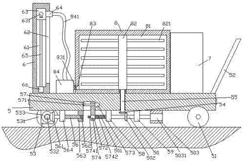
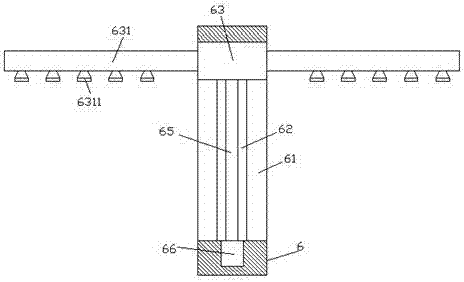
[0024] Such as Figure 1-Figure 5 As shown, an energy-saving feed feeding device of the present invention includes a frame 5 and a stirring box 8 fixed at the middle end of the top of the frame 5, and the top end surface of the frame 5 on the left side of the stirring box 8 The delivery part 6 is fixedly provided, the top end surface of the frame 5 on the right side of the stirring box 8 is fixedly provided with a power transmission part 7, and the middle end position of the frame 5 is provided with a first rotating rod 55 which is connected by rotation and fit. The extended end of the bottom of the first rotating rod 55 passes outside the bottom end surface of the frame 5 and the tail is fixed with a first conical wheel 54. The first pillar 58 and the second pillar 59 fixedly connected to the bottom end surface, the bottom end surface of the frame 5 on the right side of the second pillar 59 is fixed with a third pillar 503, and the third pillar 503 is fixed with a first pilla...


PUM


Abstract

The invention discloses an energy-saving feed throwing device. The energy-saving feed throwing device comprises a frame and a uniform stirring box, wherein the uniform stirring box is fixed to the middle end on the top of the frame. A throwing part is fixedly arranged on the top end face of the portion, on the left side of the uniform stirring box, of the frame, an electricity transmission part is fixedly arranged on the top end face of the portion, on the right side of the uniform stirring box, of the frame, a first rotary rod is arranged at the middle end in the frame and is in rotational connection with the middle end in the frame in a matched mode, the extending end on the bottom of the first rotary shaft penetrates through the bottom end face of the frame, and the tail portion of the extending end is fixedly provided with a first tapered wheel; a first supporting column and a second supporting column are arranged on the left side and right side of the first tapered wheel respectively, the tops of the first and second supporting columns are fixedly connected with the bottom end face of the frame, a third supporting column is fixedly arranged on the bottom end face of the portion, on the right side of the second supporting column, of the frame, a first motor is fixedly arranged in the third supporting column, and a second rotary rod extending to the left side is connected with the left side end of the first motor. The energy-saving feed throwing device is simple in structure and capable of achieving control switching work, meeting different requirements for different throwing work and improving the working efficiency and effect.

Description

technical field [0001] The invention relates to the field of farming of agricultural products, in particular to an energy-saving feed feeding device. Background technique [0002] In the farm, it is necessary to mix the water-soluble feed and the additive frequently and then stir it evenly. After the mixing, the traditional method usually uses manual feeding to the breeding objects, which is inefficient and time-consuming. The existing ones also have automatic feeding. The feed dispenser does not have the function of stirring, and it needs to be fed through the stirring device first, so that the work efficiency is low, and the repeated use of the mixer and the feed dispenser wastes electric energy. Contents of the invention [0003] The technical problem to be solved by the present invention is to provide an energy-saving feed feeding device, which can solve the above-mentioned problems in the prior art. [0004] The present invention is achieved through the following tec...

Claims


Application Information

Patent Timeline
Patent Type & Authority Applications(China)
IPC IPC(8): A01K5/02A01K5/00
CPCA01K5/0216A01K5/004
Inventor 付天龙
Owner 付天龙
Learn More