
A dual-circuit fan intelligent control device

An intelligent control, double-loop technology, applied in the direction of circuit devices, pump control, mechanical equipment, etc., can solve the problems of low practical performance, unrealizable, single function, etc., to solve short-time power failure, improve work efficiency, and operate Easy-to-understand effect

Active Publication Date: 2018-11-02
GUANGDONG HUAXIN MECHANICAL & ELECTRICAL INSTALLATION CO LTD
View PDF9 Cites 0 Cited by
  • Summary
  • Abstract
  • Description
  • Claims
  • Application Information

AI Technical Summary

Problems solved by technology

It is used for independent room control, hotel rooms, conference rooms, etc. The structure of the known fan automatic switching starter is composed of a vacuum contactor, a motor integrated protector, and an intermediate relay. The main fan and the backup fan are switched by the intermediate relay. It is realized by contact conversion, and the intermediate relay of the standby machine will be charged and closed when the main machine is working normally. At the same time, it cannot be realized because when the main machine is powered off and then restored, the standby machine cannot automatically switch to the main machine to work.
And the display part is only the indicator light display, which cannot visually see the operating parameters and realize the required functions.
[0003] However, the existing dual-circuit fan intelligent control device has a single function, and cannot realize the functions required by some special venues, and its practical performance is not high. The main body of the device is forced to stop working, which is a hard problem for places that need to strictly control the indoor environment. At the same time, because of a sudden power failure, when the power is restored, it will take a certain time for the host to restart, and the display part can only be displayed by the display light. Display, can not intuitively see the operating parameters and realize the required functions, electronic equipment will also appear voltage instability, leakage and other situations, which bring a certain threat to people's use safety, and bring people a lot of help few

Method used


Image

  • A dual-circuit fan intelligent control device
  • A dual-circuit fan intelligent control device

Examples


Embodiment Construction

[0018] The following will clearly and completely describe the technical solutions in the embodiments of the present invention with reference to the accompanying drawings in the embodiments of the present invention. Obviously, the described embodiments are only some, not all, embodiments of the present invention. Based on the embodiments of the present invention, all other embodiments obtained by persons of ordinary skill in the art without making creative efforts belong to the protection scope of the present invention.

[0019] see Figure 1-2 As shown, the present invention provides a kind of technical scheme:

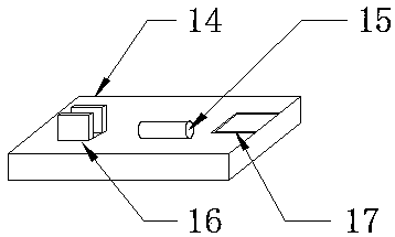
[0020] The dual-circuit fan intelligent control device of the present invention includes a device body 1 and a fan 13, a humidity sensor 2 and a vacuum contactor 3 are installed on the top of the device body 1, and the humidity sensor 2 and the vacuum contactor 3 are embedded Set in the device body 1, one side of the device body 1 is provided with a power plug 6, a f...


PUM


Abstract

The invention discloses an intelligent control device for a double-loop fan. The device comprises a device body and a ventilator. The top end of the device body is provided with a humidity sensor and a vacuum contactor. Both the humidity sensor and the vacuum contactor are embedded in the device body. One side of the device body is provided with a power plug, the ventilator and a power line. The power plug and the device body are electrically connected. The ventilator and the device body are fixedly connected through the power line. The novel intelligent control device for the double-loop fan integrates advantages of other intelligent control devices for dual-loop fans, is convenient to operate and multifunctional and has the stable power supply function. The defects that an original product has a single function, and is unstable in power supply and tedious in operation are overcome. A frequency conversion button and the vacuum contactor are arranged, multiple functions are achieved, operation is easy, and great help is brought to people

Description

technical field [0001] The invention relates to the technical field of intelligent control, in particular to an intelligent control device for a double-circuit fan. Background technique [0002] Dual-loop fresh air controller, especially suitable for fresh air units and constant temperature and humidity control. It is used for independent room control, hotel rooms, conference rooms, etc. The structure of the known fan automatic switching starter is composed of a vacuum contactor, a motor integrated protector, and an intermediate relay. The main fan and the backup fan are switched by the intermediate relay. Contact conversion is realized, and the intermediate relay of the standby machine will be charged and closed when the main machine is working normally. At the same time, it cannot be realized because when the main machine is powered off and then restored, the standby machine cannot automatically switch to the main machine to work. And the display part is only an indicator...

Claims


Application Information

Patent Timeline
Patent Type & Authority Patents(China)
IPC IPC(8): F04D27/00H02J9/06
CPCF04D27/00F04D27/008H02J9/06
Inventor 陆丽宁
Owner GUANGDONG HUAXIN MECHANICAL & ELECTRICAL INSTALLATION CO LTD
Learn More