Device, method and terminal for taking dynamic photos based on dual cameras
A dynamic photo and shooting device technology, applied in image communication, color TV parts, TV system parts, etc., can solve problems such as inaccurate focusing, affecting user experience, unclear dynamic images, etc., to improve clarity , Satisfy the effect of user experience
- Summary
- Abstract
- Description
- Claims
- Application Information
AI Technical Summary
Problems solved by technology
Method used
Image
Examples
no. 1 example
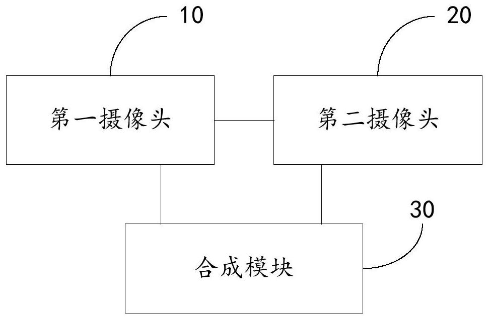
[0062] Such as image 3 As shown, the dual-camera-based dynamic photo shooting device provided in the first embodiment includes: a first camera 10 for shooting a static subject to obtain static image data; a second camera 20 for photographing a dynamic subject to obtain dynamic image data ; The synthesis module 30 synthesizes the static image data and the dynamic image data to obtain a dynamic photo. The dynamic photo shooting device of the present embodiment comprises a first camera 10, a second camera 20, and a synthesis module 30, wherein the first camera 10 and the second camera 20 obtain static image data and dynamic images after photographing static objects and dynamic objects respectively data, and finally the synthesizing module 30 synthesizes the static image data and the dynamic image data to obtain a dynamic photo. Since the shooting of the dynamic object and the shooting of the static object are respectively completed by different cameras, especially when shooting ...
no. 2 example
[0075] On the basis of the first embodiment, in the dynamic photo shooting device based on dual cameras of this embodiment, the first camera 10 is also used to: identify the focus object in the preview image; mark the focus object area where the focus object is located and focus The extension area of the object area.
[0076] When using a mobile phone to take a dynamic photo, first turn on the dynamic photo shooting mode, use the first camera to identify the focus object in the preview image, mark the focus object area where the focus object is located and the extension area of the focus object area, and the extension area of the extension area The range should be appropriate, and the specific extension range can refer to related disclosed technical solutions in the prior art. After marking the focus object area where the focus object is located and the extended area of the focus object area, the first camera 10 takes a still photo to obtain the first image.
no. 3 example
[0078] On the basis of the second embodiment, the second camera 20 is specifically used to: use the focus object area and the extended area of the focus object area as the video focus area to shoot a dynamic object, and the recording time period for shooting the dynamic object is T .
[0079] The second camera 20 uses the focus area where the focus object marked by the first camera 10 is located and the extended area of the focus area as the video focus area to shoot a dynamic subject, in order to enhance the accuracy of shooting a dynamic subject.
PUM
 Abstract
Description
Claims
Application Information
 - R&D
- Intellectual Property
- Life Sciences
- Materials
- Tech Scout
- Unparalleled Data Quality
- Higher Quality Content
- 60% Fewer Hallucinations
Browse by: Latest US Patents, China's latest patents, Technical Efficacy Thesaurus, Application Domain, Technology Topic, Popular Technical Reports.
© 2025 PatSnap. All rights reserved.Legal|Privacy policy|Modern Slavery Act Transparency Statement|Sitemap|About US| Contact US: help@patsnap.com


