
A power supply device

A technology of electric power supply and socket, which is applied in the field of electric power, can solve problems such as potential safety hazards, easily induced electric shock accidents, poor contact, etc., and achieves the effects of high safety and stability, reduced personnel touch, and convenient operation

Active Publication Date: 2018-08-10
江苏凯顺电气有限公司
View PDF4 Cites 0 Cited by
  • Summary
  • Abstract
  • Description
  • Claims
  • Application Information

AI Technical Summary

Problems solved by technology

[0002] The power supply device is an important part of the power equipment. It is mainly composed of a plug part and a socket part and is connected to the power supply by manual plugging. Since the existing power supply device does not have any protective structure when plugging in , when the air humidity is high or the hands are stained with water, it is very easy to induce electric shock accidents, and there is a great safety hazard. Other external factors make the plug loose, resulting in poor contact, unable to work normally with power supply, there are major disadvantages, and cannot meet the existing needs

Method used


Image

  • A power supply device
  • A power supply device
  • A power supply device

Examples


Embodiment Construction

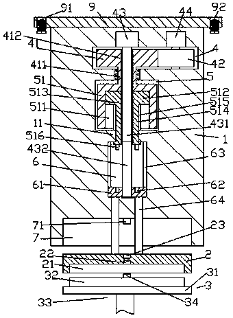
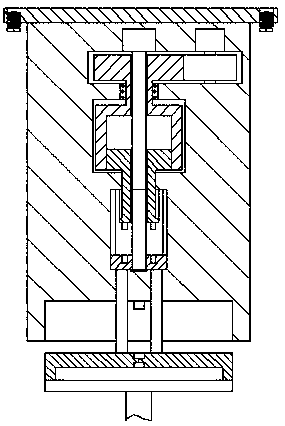
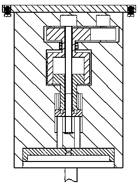
[0020] Such as Figure 1-Figure 4 As shown, an electric power supply device according to the present invention includes a socket part 1 and a plug part 3 arranged below the bottom of the socket part 1, and the inside of the socket part 1 is sequentially provided with a first accommodating chamber 4, The second accommodation chamber 5 and the third accommodation chamber 6, the bottom end surface of the socket part 1 is provided with an engaging groove 7, the first accommodation chamber 4 is provided with a first toothed wheel 41, and the first toothed wheel The right side of 41 is occluded with a second toothed wheel 42, the top of the second toothed wheel 42 is connected to the first motor 44, and the bottom of the first toothed wheel 41 is provided through the wall of the socket part 1 and Enter the rotating shaft 411 in the second receiving chamber 5, the second receiving chamber 5 is provided with a casing 51 whose top is fixedly connected with the rotating shaft 411, and t...


PUM


Abstract

The invention discloses a novel electric-power power supply apparatus. The novel electric-power power supply apparatus comprises a socket part and a plug part which is inserted and connected below the bottom of the socket part; a first accommodating cavity, a second accommodating cavity and a third accommodating cavity are formed in the socket part from top to bottom in sequence; a combining groove is formed in the bottom end plane of the socket part; a first tooth-shaped wheel is arranged in the first accommodating cavity; the right side of the first tooth-shaped wheel is connected with a second tooth-shaped wheel in an occlusion manner; the top of the second tooth-shaped wheel is connected with a first electric motor; a rotary shaft which penetrates through the wall body of the socket body and enters the second accommodating cavity is arranged at the bottom of the first tooth-shaped wheel; a sleeve shell, the top of which is fixedly connected with the rotary shaft, is arranged in the second accommodating cavity; an inner spiral whorl cavity is formed in the sleeve shell; a telescopic block is matched and connected in the inner spiral whorl cavity in an inner spiral whorl manner; a first through groove, which is formed in an up and down penetration manner, is formed in the telescopic block; a second through groove, which is formed in an up and down penetration manner, is formed in the first tooth-shaped wheel and the rotary shaft; a rotary pin shaft, which is arranged in an up and down extension manner, is arranged in the second through groove; the top end of the rotary pin shaft is connected with a second electric motor; an extension section at the bottom of the rotary pin shaft passes through the second through groove and the inner spiral whorl cavity to enter the third accommodating cavity.

Description

technical field [0001] The invention relates to the field of electric power technology, in particular to an electric power supply device. Background technique [0002] The power supply device is an important part of the power equipment. It is mainly composed of a plug part and a socket part and is connected to the power supply by manual plugging. Since the existing power supply device does not have any protective structure when plugging in , when the air humidity is high or the hands are stained with water, it is very easy to induce electric shock accidents, and there is a great safety hazard. The external factors such as the influence make the plug connection loose, resulting in poor contact, unable to work normally with power supply, which has great disadvantages and cannot meet the existing needs. Contents of the invention [0003] The technical problem to be solved by the present invention is to provide an electric power supply device, which can solve the above-mentio...

Claims


Application Information

Patent Timeline
Patent Type & Authority Patents(China)
IPC IPC(8): H01R13/44H01R13/627H01R13/629
CPCH01R13/44H01R13/627H01R13/629
Inventor 戎传龙
Owner 江苏凯顺电气有限公司
Learn More