
Deflection type working device structure of excavator and for tunnel

A technology for working devices and excavators, applied to mechanically driven excavators/dredgers, etc., can solve problems such as unguaranteed efficiency, high after-sales service costs, easy damage to pipelines and other components, and achieve the effect of convenient and fast transfer

Inactive Publication Date: 2017-05-31
XCMG EXCAVATOR MACHINERY
View PDF11 Cites 5 Cited by
  • Summary
  • Abstract
  • Description
  • Claims
  • Application Information

AI Technical Summary

Problems solved by technology

However, due to the limitation of the structural design of the boom and stick in the working device, when the bucket teeth are raised to a height of 4m, the boom stick has touched the top of the tunnel, and the top material cannot be excavated any more.
At the same time, the width of the tunnel is narrow. In the tunnel, the excavator cannot rotate in a large range. Generally, the arched edge of the tunnel cannot be swept by the excavator. Manpower is required to assist the operation, which cannot guarantee efficiency and wastes time and money.
[0004] In addition, due to the harsh working conditions, components such as oil cylinders and pipelines on the working equipment are easily damaged, and it is not easy to directly replace components in the tunnel. It is necessary to exit the tunnel and replace components outside. The cost of after-sales service is high and serious. Affected the construction progress of the project

Method used


Image

  • Deflection type working device structure of excavator and for tunnel
  • Deflection type working device structure of excavator and for tunnel

Examples


Embodiment Construction

[0017] The present invention will be further described below in conjunction with accompanying drawing.

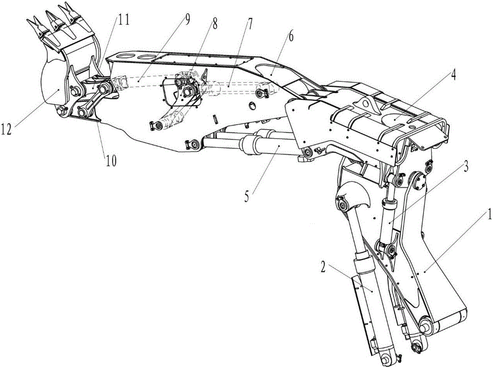
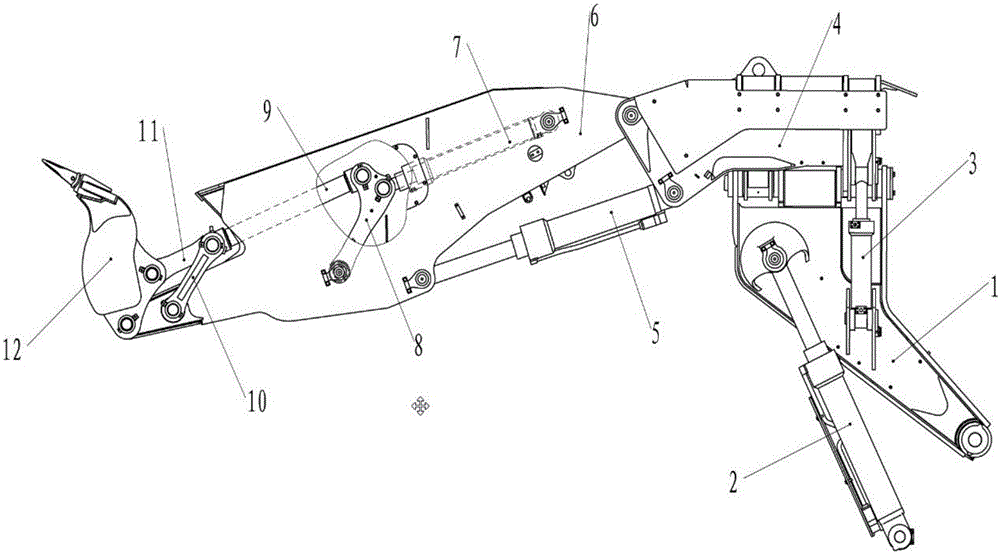
[0018] Such as figure 1 with figure 2 As shown, a deflection type working device structure for an excavator tunnel includes a bottom boom 1, a boom cylinder 2, a deflection cylinder 3, a deflection boom 4, an arm cylinder 5, an arm 6, a bucket cylinder 7, an inner rocker 8, rocker link 9, outer rocker 10, outer link 11 and bucket 12, the cylinder head of the boom cylinder 2 is connected to the front of the bottom boom 1, and the bottom boom 1 The upper part is connected with the lower part of the deflection boom 4, two deflection cylinders 3 are symmetrically arranged on both sides of the bottom boom 1 and the deflection boom 4, the cylinder body of the deflection cylinder 3 is connected with the side of the bottom boom 1, and the cylinder head is connected with the deflection The side of the rotating arm 4 is connected; the upper front side of the deflection rotating ar...


PUM


Abstract

The invention discloses a deflection type working device structure of an excavator and for a tunnel. The deflection type working device structure comprises a bottom movable arm, movable arm oil cylinders, deflection oil cylinders, a deflection movable arm, bucket rod oil cylinders, a bucket rod, a bucket oil cylinder, an inner rocker, a rocker arm connecting rod, an outer rocker, an outer connecting rod and a bucket. The movable arm oil cylinders are connected with the bottom movable arm, the bottom movable arm is connected with the deflection movable arm, and the deflection oil cylinders are connected with the bottom movable arm and the deflection movable arm. The upper side of the front portion of the deflection movable arm is connected with the root of the bucket rod, the front portion of the bucket rod is connected with the bucket, and the bucket oil cylinder is connected to the deflection movable arm and the bucket rod. The bucket rod oil cylinders, the inner rocker and the rocker arm connecting rod are arranged inside the bucket rod. According to the deflection type working device structure of the excavator and for the tunnel, a working device can be freely subjected to deflection, and no dead corner operation can be conducted; top operation is implemented in a barrier-free mode, arch shape-repairing operation can be conducted, and the phenomenon that operation cannot be achieved does not need to be worried; comprehensive protection design is achieved, and damage caused to special parts by falling objects does not need to be worried; whole machine transferring is more convenient and quick; and therefore, construction operation of the tunnel is more convenient, quick and efficient.

Description

technical field [0001] The invention relates to a deflection type working device structure for an excavator tunnel, belonging to the technical field of excavators. Background technique [0002] In daily construction production, excavators are often used for excavation, loading, crushing or demolition operations. As a device that directly completes the above tasks, the working device includes the three major structural parts of the boom, stick, and bucket, as well as small parts such as hydraulic cylinders, hydraulic lines, rockers, and connecting rods. Among them, the graph formed by the range that can be reached between the bucket teeth of the working device is called the envelope graph. In other words, any point inside the envelope can be reached by the working device bucket. Therefore, in theory, during the working process of the excavator, all points within the excavation range can be excavated. [0003] However, in actual work, due to the limitation of the working en...

Claims


Application Information

Patent Timeline
IPC IPC(8): E02F3/28E02F3/38E02F3/42
CPCE02F3/28E02F3/38E02F3/42
Inventor 王全永杨裕丰耿家文马瑞永刘刚强历娜王存珍朱金孟董步军杨晓磊董玉忠秦满义姚锡涛张马永徐立明宗波
Owner XCMG EXCAVATOR MACHINERY
Learn More