Robot head structure and robot
A robot and head technology, applied in the field of robots, can solve the problems of large operation space, complex structure, complicated operation, etc., and achieve the effect of good continuity, high mechanical strength and motion accuracy, and avoid unresponsiveness.
- Summary
- Abstract
- Description
- Claims
- Application Information
AI Technical Summary
Problems solved by technology
Method used
Image
Examples
Embodiment 1
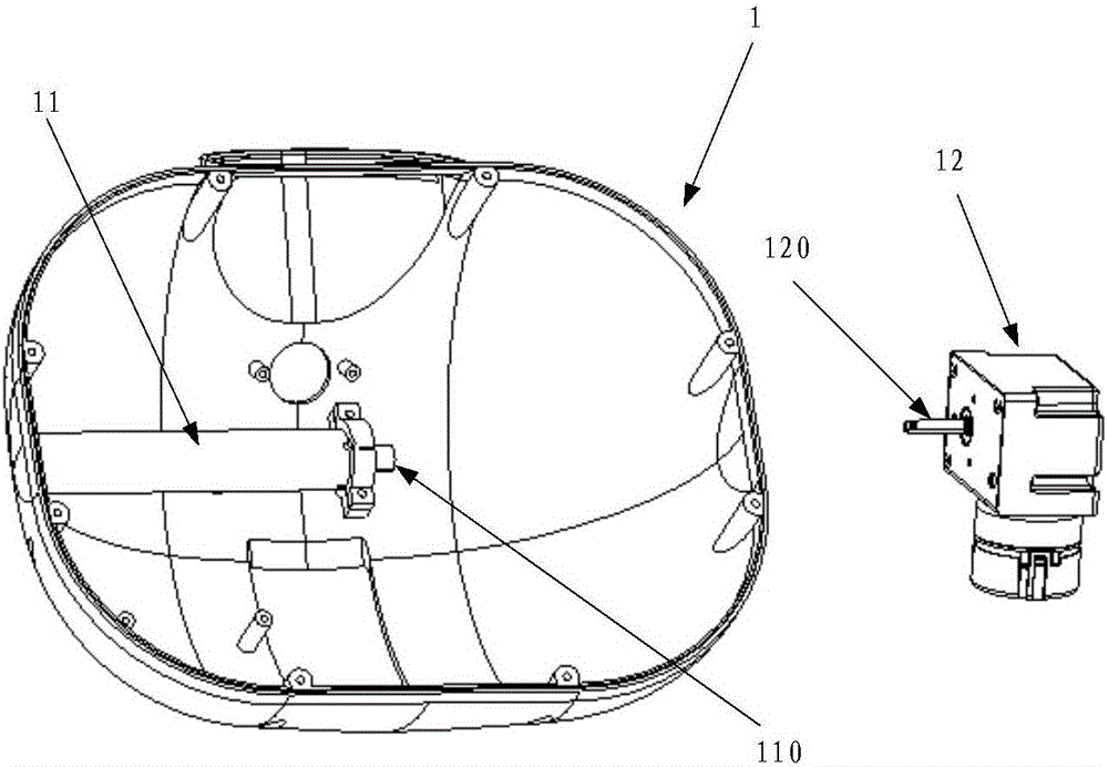
[0019] figure 1 It is a schematic diagram of a robot head structure according to an embodiment of the present invention, see figure 1 The robot head structure 1 of this embodiment includes: a head housing, a rotating shaft 11 and a motor 12 for driving the rotating shaft 11,
[0020] The rotating shaft 11 is installed on the head housing, and one end of the rotating shaft 11 has a shaft hole 110, and the motor shaft 120 of the motor 12 is inserted in the shaft hole 110 of the rotating shaft 11; the rotating shaft 11 is provided with a first through hole, and the motor shaft 120 is provided with a second through hole,
[0021] The robot head structure also includes a first fastener. After the motor shaft 120 is inserted into the shaft hole 110 of the rotating shaft, the positions of the second through hole correspond to the first through hole, and the first fastener passes through the first through hole. and the second through hole, the motor shaft 120 is installed in the sha...
Embodiment 2
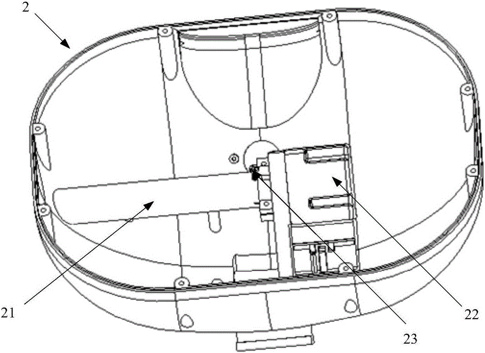
[0025] figure 2 It is a schematic diagram of the rotating shaft connected to the motor of a robot head structure according to an embodiment of the present invention, image 3 It is a schematic diagram of the rotating shaft of a robot head structure not connected to the motor according to an embodiment of the present invention, Figure 4 is a schematic diagram of a rotating shaft in an embodiment of the present invention, Figure 5 It is a schematic diagram of a motor according to an embodiment of the present invention. The following combination Figure 2 to Figure 5 The structure of the robot head of this embodiment will be specifically described.
[0026] see figure 2 and image 3 , the robot head structure includes a head shell 20, the head shell 20 is provided with a movable passage 201, the motor 22 is fixedly connected with the body of the robot through the movable passage 201, and is stationary relative to the fuselage, the rotating shaft 21 and the head The casi...
Embodiment 3
[0051] Image 6 is a schematic diagram of a robot according to an embodiment of the present invention, see Image 6 , the robot includes a body 62 and a robot head structure 61 connected to the body 62 .
[0052] It should be noted that the head structure of the robot in this embodiment adopts the head structure of the robot in the foregoing embodiments. Therefore, the robot of this embodiment has a simple and compact structure, can adjust the movement angle at will, has high movement precision, and the head movement is more anthropomorphic. The volume can be designed smaller and the cost is lower.
[0053] In summary, the robot head structure of the embodiment of the present invention has the following advantages:
[0054] (1) The assembly of the motor and the rotating shaft does not require bearings and related structural parts, and the cost is low, the flexibility is good, the installation is convenient, the required assembly space is small, and the mechanical strength a...
PUM
 Abstract
Description
Claims
Application Information
 - R&D Engineer
- R&D Manager
- IP Professional
- Industry Leading Data Capabilities
- Powerful AI technology
- Patent DNA Extraction
Browse by: Latest US Patents, China's latest patents, Technical Efficacy Thesaurus, Application Domain, Technology Topic, Popular Technical Reports.
© 2024 PatSnap. All rights reserved.Legal|Privacy policy|Modern Slavery Act Transparency Statement|Sitemap|About US| Contact US: help@patsnap.com


