
Watch spring winding apparatus

A technology of watches and automatic watches, applied in the direction of automatic winding, clocks, clockwork ratchet mechanisms, etc., can solve problems such as large spaces, and achieve the effect of improving transmission

Inactive Publication Date: 2017-05-17
M & E UHRENBEWEGER MANUFAKTUR
View PDF9 Cites 2 Cited by
  • Summary
  • Abstract
  • Description
  • Claims
  • Application Information

AI Technical Summary

Problems solved by technology

However, the arrangement takes up a relatively large amount of space since it is more like a piece of furniture
[0007] In the prior art, the simple movement of a watch is only described for a single watch or a very small number of watches, while the synchronous movement of multiple watches can only be realized through a very complex mechanical mechanism

Method used


Image

  • Watch spring winding apparatus
  • Watch spring winding apparatus
  • Watch spring winding apparatus

Examples


Embodiment Construction

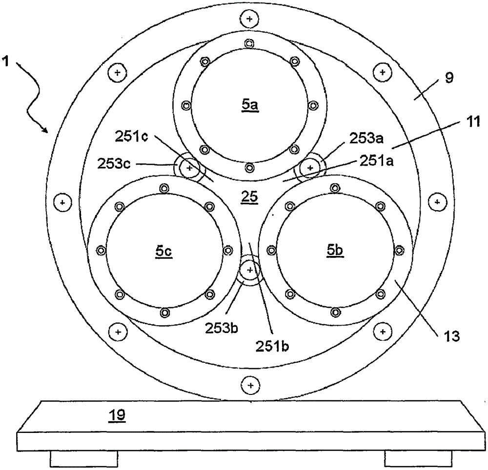
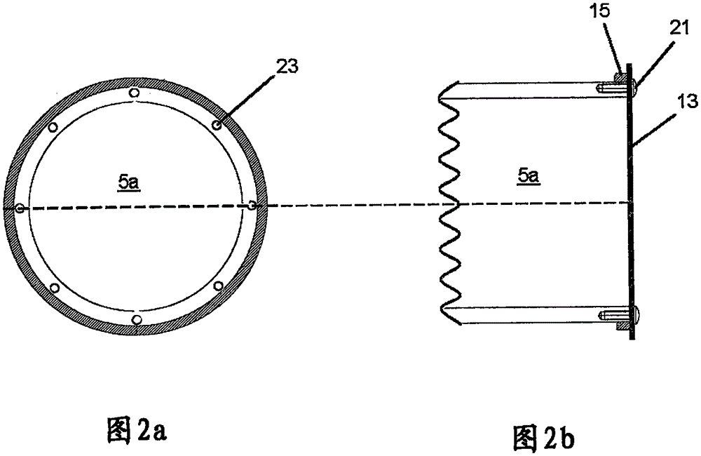
[0091] exist figure 1 In , a first embodiment of a first variant of the invention of a watch winding device 1 according to the invention is shown. The transmission element 25 is arranged centrally therein. Arranged around the transmission element are three receiving cylinders 5a, 5b, 5c, said receiving cylinders being in a corresponding position by their lateral surfaces with the transmission element 25, more precisely with the rotation elements 253a, 253b, 253c. Force locked contact. However, the receiving cylinders 5a, 5b, 5c are spaced at a distance from each other. This ensures that the rotational movement of the transmission element 25 converted into a relative rotational movement of the receiving cylinders 5a, 5b, 5c is not inhibited. The receiving cylinders 5a, 5b, 5c form an arrangement plane. By the rotational movement of the transmission element 25 , the receiving cylinders 5 a , 5 b , 5 c all rotate about their longitudinal axes and also move on a circular path ...


PUM


Abstract

The invention relates to a watch spring winding apparatus (1) which comprises a transmission component (25) mounted along the longitudinal axis of the apparatus in a rotation manner, a motor (27) to drive the transmission component (25) mounted along the longitudinal axis of the apparatus, a plurality of collection cylinder bodies (5a, 5b, 5c, 5d, 5e, and 5f) mounted along the longitudinal axis of the apparatus also in a rotation manner, and at least one housing component (9) with an almost round opening (11). The plurality of collection cylinder bodies and the transmission components are held in the opening (11) in a paired manner wherein the collection cylinder bodies with the guided manner are mutually independent from each other and can rotate around the transmission component (25) and are arranged on the concentric circle path (K1) in a rotation manner to make sure that the transmission component is in a force locked contact wherein the collection cylinder bodies and the almost round opening (11) of the housing component (9) are in the force locked contact. The invention also discloses a method for winding the spring of a mechanical automatic watch by using the watch spring winding apparatus proposed by the invention.

Description

technical field [0001] The invention relates to a watch winding device having a plurality of receiving cylinders for receiving a watch and allowing a very uniform movement of the watch for winding a mechanical movement. Background technique [0002] Watch winding devices are generally used to wind mechanical automatic watches. Such mechanical automatic watches are designed in principle to be wound continuously by being worn on the wrist and the resulting movement. Once the watch is fully wound, that is to say the driving spring of the watch mechanism is fully pretensioned, ensuring a running time or power reserve of 20-40 hours, depending on the construction and scope of functions of the watch. When the watch is not being worn, that is to say when no regular movement takes place, the movement stops at the end of the power reserve and the watch has to be wound manually. [0003] However, a watch stop makes it necessary not only to set the current time, but especially in the...

Claims


Application Information

Patent Timeline
Patent Type & Authority Applications(China)
IPC IPC(8): G04B5/02
CPCG04B5/02
Inventor O·埃斯佩纳A·默克林格
Owner M & E UHRENBEWEGER MANUFAKTUR
Learn More