
Robot inter-detection method and robot inter-detection device

A detection method and detection device technology, applied in the field of robotics, can solve the problems that the robot cannot detect the position, affect the operation of the robot, and cannot see the overall outline of the robot, etc.

Active Publication Date: 2017-05-10
深圳优地科技有限公司
View PDF7 Cites 23 Cited by
  • Summary
  • Abstract
  • Description
  • Claims
  • Application Information

AI Technical Summary

Problems solved by technology

A robot equipped with lidar must be hollowed out so that the rays of the lidar can be emitted to detect obstacles in the environment. Therefore, when multiple robots are running on the same floor indoors, one robot can only see the other. The robot's radar, but cannot see the overall outline of other robots
However, the physical size of the radar is still too small compared to the overall outline of the robot, which makes it impossible for the robots to perform accurate position detection with each other, which affects the operation of the robot indoors

Method used


Image

  • Robot inter-detection method and robot inter-detection device
  • Robot inter-detection method and robot inter-detection device

Examples


Embodiment 1

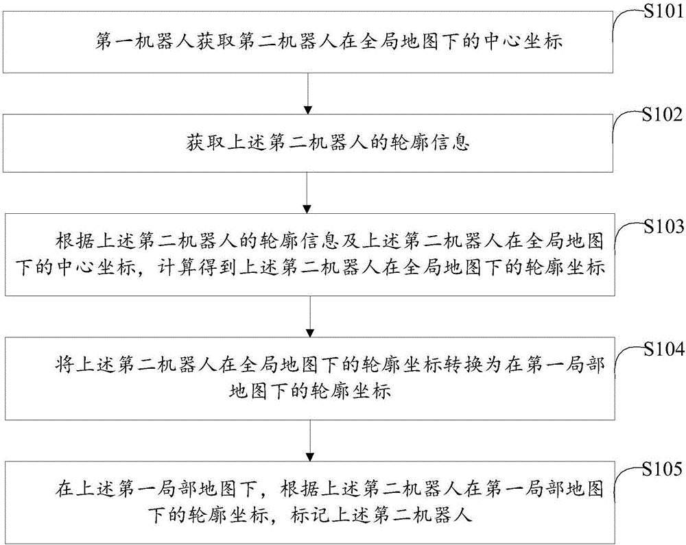
[0023] figure 1 The implementation flow of the robot mutual detection method provided by Embodiment 1 of the present invention is shown, and the details are as follows:

[0024] In step S101, the first robot acquires the center coordinates of the second robot under the global map.

[0025] In the embodiment of the present invention, in order to better illustrate the solution of the embodiment of the present invention, a first robot and a second robot are briefly introduced first. Among all the robots in the same building, select any one of them as the first robot in the embodiment of the present invention, and use the solution of the embodiment of the present invention to detect the positions of other robots. Since the present invention provides a method for mutual detection of robots, all other robots except the above-mentioned first robot can be used as the second robot. In fact, since any robot can detect other robots using the solution of the embodiment of the present in...

Embodiment 2

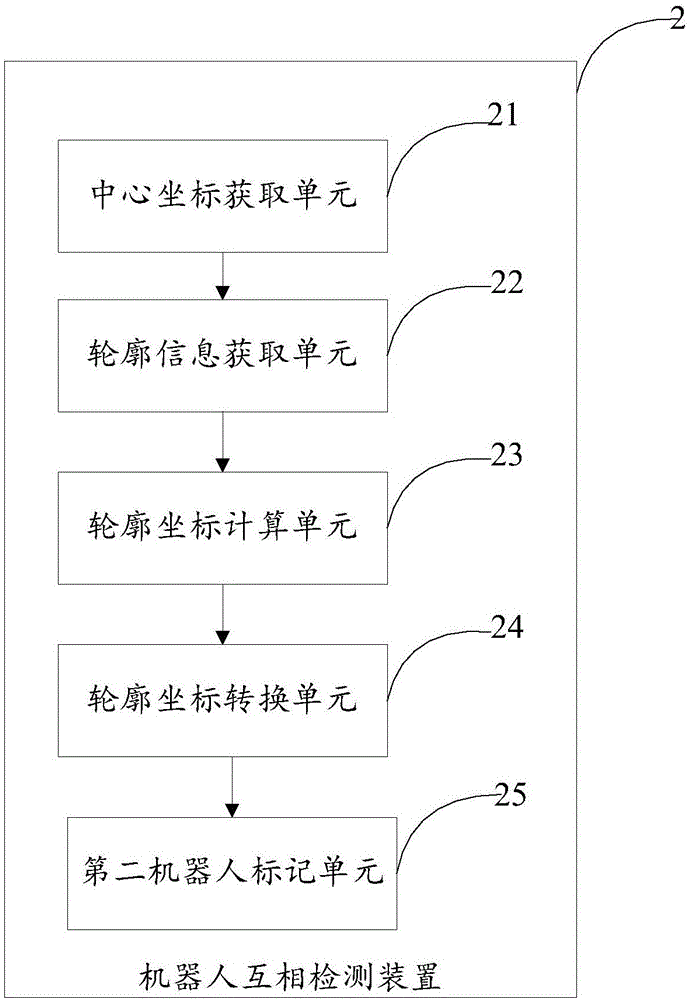
[0047] figure 2 A specific structural block diagram of the robot mutual detection device provided by the second embodiment of the present invention is shown, and for the convenience of description, only the parts related to the embodiment of the present invention are shown. The robot mutual detection device 2 includes: a central coordinate acquisition unit 21 , a contour information acquisition unit 22 , a contour coordinate calculation unit 23 , a contour coordinate conversion unit 24 , and a second robot marking unit 25 .

[0048] Wherein, the central coordinate acquisition unit 21 is used to acquire the central coordinates of the second robot under the global map;

[0049] An outline information acquiring unit 22, configured to acquire the outline information of the above-mentioned second robot;

[0050] The contour coordinate calculation unit 23 is used to calculate and obtain the above-mentioned second robot according to the contour information of the second robot obtai...


PUM


Abstract

The invention discloses a robot inter-detection method and a robot inter-detection device. The robot inter-detection method includes the following steps: a first robot acquires central coordinates of a second robot in a global map; the profile information of the second robot is acquired; profile coordinates of the second robot in the global map are worked out according to the profile information of the second robot and the central coordinates of the second robot in the global map; the profile coordinates of the second robot in the global map are converted into profile coordinates in a first local map, wherein the first local map is a local map of the first robot; and the second robot in the first local map is marked according to the profile coordinates of the second robot in the first local map. The solution of the invention can ensure that a plurality of single-line laser radar robots operating in the same building can quickly and accurately detect the position of one another, thus guaranteeing the normal operation of the plurality of robots.

Description

technical field [0001] The invention relates to the field of robots, in particular to a method and device for mutual detection of robots. Background technique [0002] When indoor robots are navigating, they need to detect the surrounding environment in real time. At present, there are two main types of sensors used by indoor mobile robots: one is RGB depth (Red Green Blue Depth, RGB-D) camera or binocular camera, and the other is lidar. Since the RGB-D camera uses image information or point cloud information as raw data for obstacle detection, resulting in a large amount of computing data, and the result is easily affected by indoor light, and its robustness is poor. Compared with RGB-D cameras, lidar has the characteristics of accurate data, not affected by ambient light, and small data volume, so it is widely used in indoor robots as the "eyes" of indoor robots. Because of the high cost of multi-line lidar, single-line lidar is generally used at present. A robot equipp...

Claims


Application Information

Patent Timeline
IPC IPC(8): G01C21/00G01C21/20
CPCG01C21/005G01C21/206
Inventor 焦小亮李超曹立冬刘文泽夏舸顾震江
Owner 深圳优地科技有限公司
Learn More