Eureka AIR delivers breakthrough ideas for toughest innovation challenges, trusted by R&D personnel around the world.

Binding system for concrete hollow building block wall piece in agglomeration building and binding method thereof

A technology of hollow blocks and concrete, which is applied in construction, building structure, and processing of building materials, etc., and can solve problems such as the inability to realize the hoisting of hollow block wall pieces and the inconvenience of construction

Active Publication Date: 2017-04-26
HARBIN DACHENG GREEN BUILDING TECH DEV
View PDF6 Cites 3 Cited by
  • Summary
  • Abstract
  • Description
  • Claims
  • Application Information

AI Technical Summary

Problems solved by technology

[0004] The purpose of the present invention is to solve the problem that the existing two-point hoisting method cannot realize the hoisting of hollow block wall pieces, which brings inconvenience to the construction site

Method used


Image

  • Binding system for concrete hollow building block wall piece in agglomeration building and binding method thereof
  • Binding system for concrete hollow building block wall piece in agglomeration building and binding method thereof
  • Binding system for concrete hollow building block wall piece in agglomeration building and binding method thereof

Examples


specific Embodiment approach 1

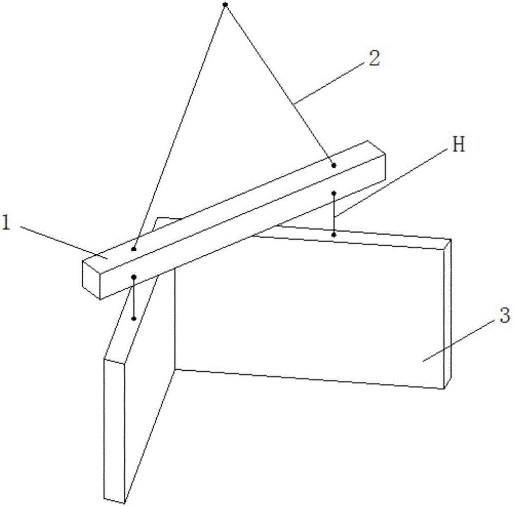
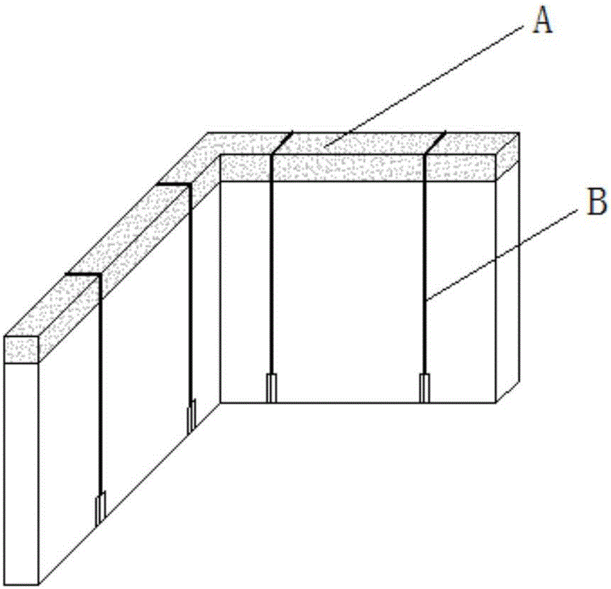
[0029] Specific implementation mode one: combine Figure 1 to Figure 13 Describe this embodiment, a kind of concrete hollow block wall piece binding system of agglomerate building in this embodiment includes binding beam A, multiple binding pieces B, slider C, balance beam 1 and hoisting rope 2, binding beam A passes through multiple A binding part B is bound on the wall piece 3, the balance beam 1 is located above the binding beam A and the balance beam 1 and the binding beam A are connected by a lifting rope H, and one end of the lifting rope 2 is connected to one side of the binding beam A, The other end of the hoisting rope 2 is connected to the other side of the binding beam A, and the connection between the hoisting rope 2 and the binding beam A is slidably connected through a slider C.

[0030] The binding system of this embodiment adopts a balance beam on the top, and the entire wall piece is bound on the balance beam with a hoisting rope, and the wall piece can be hoi...

specific Embodiment approach 2

[0031] Specific implementation mode two: combination Figure 3 to Figure 7 To illustrate this embodiment, the binding beam A of this embodiment includes an in-line binding beam, an L-shaped binding beam, a Z-shaped binding beam or a T-shaped binding beam formed by connecting a plurality of standard sections. With such a setting, it is convenient to select a binding beam of a suitable shape according to different conditions in the actual construction process, and can be connected with various prefabricated parts of different shapes, so as to realize smooth and safe hoisting in various situations. Other compositions and connections are the same as in the first embodiment.

specific Embodiment approach 3

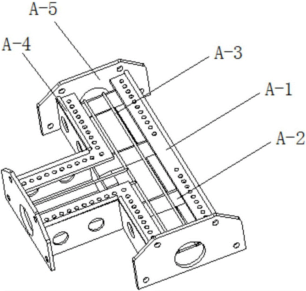
[0032] Specific implementation mode three: combination Figure 3 to Figure 7 To illustrate this embodiment, the standard section of this embodiment includes two channel steel A-1, two steel bars A-3, two round steel pipes A-4, multiple reinforcing ribs A-2 and at least one connecting plate A-5 , the open ends of the two channel steels A-1 are set opposite to each other, and the two channel steels A-1 are connected by a plurality of reinforcing ribs A-2 vertically installed in the grooves of the two channel steels A-1. Reinforcement A-3 is parallel to the length direction of two channel steels A-1 and is fixedly installed on multiple reinforcing ribs A-2 inside the two channel steels A-1, and two round steel pipes A-4 are fixedly installed in two channels The upper end of the steel A-1 is close to the corner, and the two ends of the two channel steel A-1 are connected with at least one connecting plate A-5. Such setting provides a basic standard joint, which is convenient for ...


PUM


Abstract

The invention provides a binding system for a concrete hollow building block wall piece in an agglomeration building and a binding method thereof and relates to a binding system and a binding method. According to the binding system for the concrete hollow building block wall piece in the agglomeration building and the binding method thereof, the problem that lifting of the hollow building block wall piece cannot be achieved by an existing two-lifting-point lifting method, and thus inconvenience is brought to site construction is solved. According to the binding system for the concrete hollow building block wall piece in the agglomeration building, a binding beam is bound on the wall piece through a plurality of binding parts, a balance beam is located above the binding beam, and the balance beam and the binding beam are connected through lifting ropes. One end of each lifting rope is connected to one side of the binding beam, the other end of each lifting rope is connected to the other side of the binding beam, and the joints of the lifting ropes and the binding beam are slidingly connected through sliding blocks. The binding method comprises the following steps that the binding beam is connected; the sliding blocks are slidingly arranged on the binding beam; the binding beam and the concrete hollow building block wall piece are bound together through the binding parts; the balance beam and the binding beam are connected; and the lifting ropes are installed, and lifting is conducted. The binding system for the concrete hollow building block wall piece in the agglomeration building and the binding method thereof are applied to the construction industry.

Description

technical field [0001] The invention relates to a wall piece binding system and a binding method, in particular to a wall piece binding system and a binding method of a concrete hollow block wall of an aggregate building. Background technique [0002] In recent years, with the acceleration of construction industrialization and housing industrialization, prefabricated concrete structures have undergone new developments in the new era. For example, PC structure and fully prefabricated integral concrete shear wall structure have achieved good economic and social benefits in the process of application and promotion. According to statistics, the rate of development and construction of prefabricated structures in newly-built commercial housing in Shanghai, Shenyang and other cities with relatively developed housing industrialization has reached 20-30%, and will achieve greater development in the next few years. In summary, it can be seen that prefabricated construction will be th...

Claims


Application Information

Patent Timeline
Patent Type & Authority Applications(China)
IPC IPC(8): E04G21/16B66C1/12
CPCB66C1/12E04G21/167
Inventor 王凤来
Owner HARBIN DACHENG GREEN BUILDING TECH DEV
Why Eureka
Eureka Blog
Learn More