
Photoelectric composite underwater plug connector

A plug-in connector, optoelectronic composite technology, applied in the direction of connection, two-part connection device, and components of the connection device, etc., can solve the problems of large workload, high installation cost, inconvenience, etc., to reduce workload, reduce The effect of laying costs

Active Publication Date: 2018-08-31
8TH RES INST OF CETC
View PDF3 Cites 3 Cited by
  • Summary
  • Abstract
  • Description
  • Claims
  • Application Information

AI Technical Summary

Problems solved by technology

[0003] Conventional photoelectric composite underwater plug-in connectors generally include plugs and sockets. The transmission of photoelectric information is realized through the insertion of plugs and sockets. The operation is relatively simple. However, due to the constraints of current sealing technology, the existing underwater photoelectric composite connections The connector can only be docked with the plug and socket on the land bank or on the water surface, and then put it into the water as a whole to work, and it cannot be plugged and unplugged underwater. This is very difficult for system laying, because the plugged connector needs to be Putting the entire system into the water requires a considerable amount of work and high laying costs. In addition, when repairing or replacing other underwater equipment, the entire system needs to be pulled out again, which is very inconvenient

Method used


Image

  • Photoelectric composite underwater plug connector
  • Photoelectric composite underwater plug connector
  • Photoelectric composite underwater plug connector

Examples


Embodiment Construction

[0029] The photoelectric composite underwater plug connector of the present invention will be further described in detail in conjunction with the accompanying drawings and specific embodiments:

[0030] For the convenience of description, the "left" and "right" mentioned below are consistent with the left and right directions of the drawings themselves.

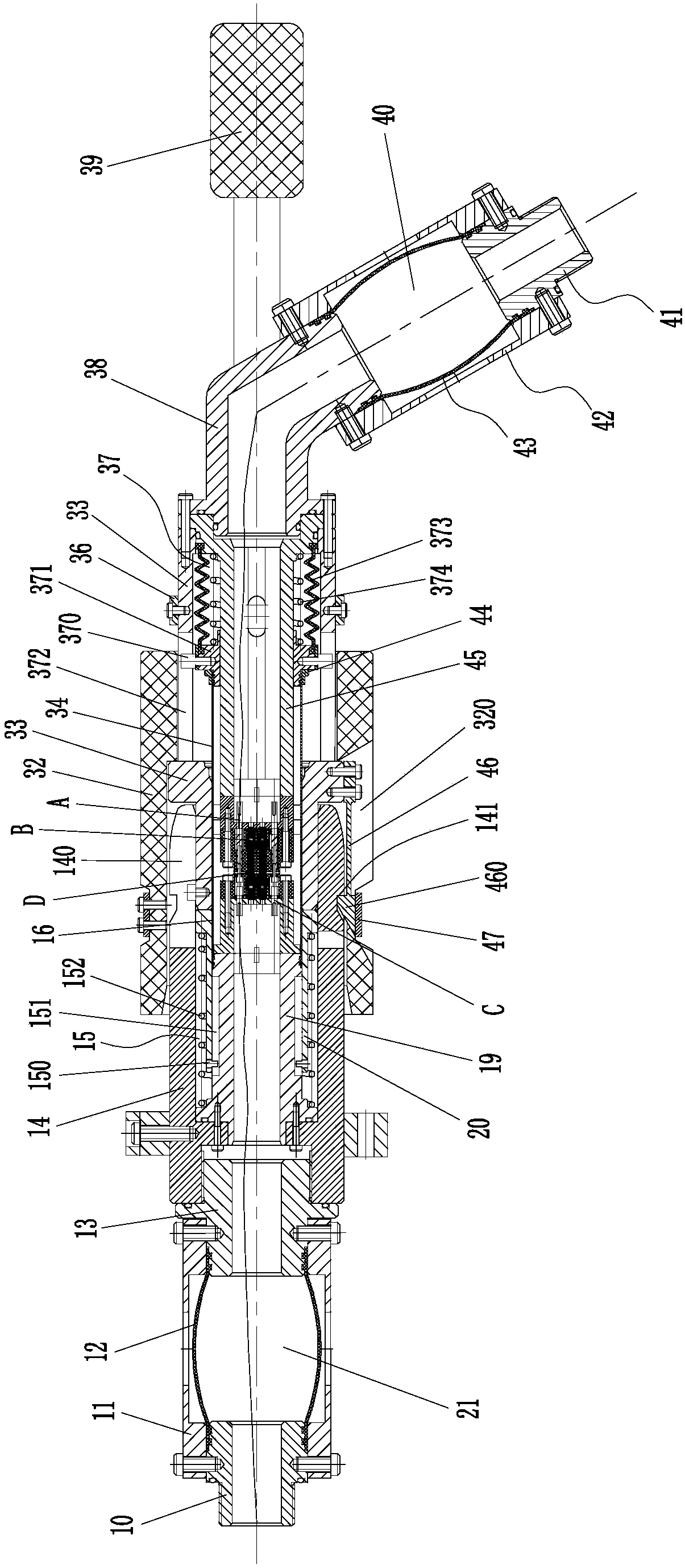
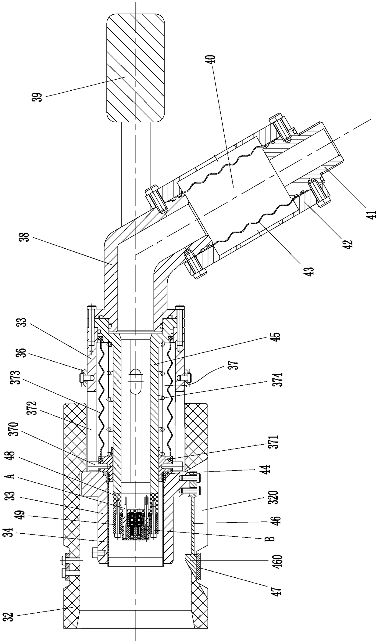
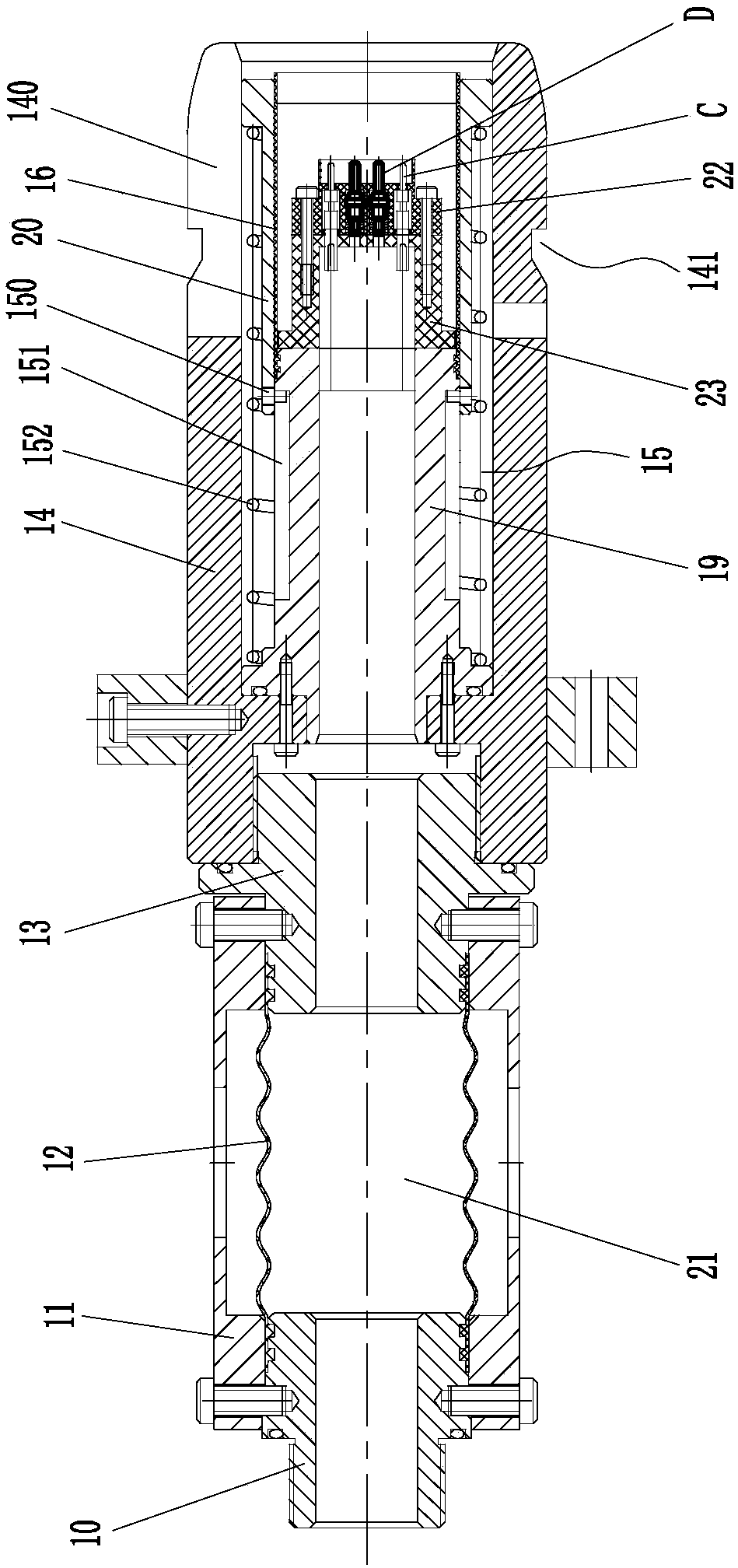
[0031] like figure 1 , figure 2 and image 3As shown, in this specific embodiment, the photoelectric composite underwater plug connector of the present invention includes a plug and a socket, wherein the plug includes an outer shell 32, a plug shell 33, a first lip seal 34, an electric pin A , fiber ferrule B, plug core body 45, first tail connector 41 and first adapter seat 38, the outer casing 32 is set on the plug housing 33, the first lip seal 34 and the plug core body 45 are located In the inner cavity of the plug housing 33, the first lip seal 34 is set on the outside of the plug core 45, and a first reset device 37...


PUM


Abstract

The invention relates to a photoelectric underwater plugging connector. A plug is composed of an outer shell, a plug housing, a plug core, a first lip-shaped sealing element, an electrical contact pin A, a fiber plugging core B, a first adapter base and a first tail connecting element. A socket consists of a second tail connecting element, a second adapter base, a socket housing, a socket core, a socket sliding block, a second lip-shaped sealing element, an electrical contact pin C and a fiber plugging core D. When extending out of the inner cavity of the plug housing slightly, the left end of the first lip-shaped sealing element is closed and sealed; when retracting into the inner cavity of the plug housing, the left end of the first lip-shaped sealing element opens; when extending into the inner cavity of the socket sliding block, the right end of the second lip-shaped sealing element is closed and sealed; and when the socket sliding block separates from the right end of the second lip-shaped sealing element, the right end of the second lip-shaped sealing element opens and the outer shell and the socket housing are buckled and connected. Therefore, the operation is simple; underwater plugging is realized; the workload is reduced substantially; and underwater equipment can be repaired or replaced conveniently.

Description

technical field [0001] The invention relates to the field of underwater detection, in particular to a photoelectric composite underwater plug-in connector for underwater signal transmission. Background technique [0002] Due to the needs of the military and the further exploration and development of marine resources, photoelectric composite underwater plug connectors, as an indispensable and important part of underwater systems, are increasingly used underwater. At present, underwater plug-in connectors are widely used in underwater large-scale engineering projects such as underwater detection arrays, port acoustic-magnetic monitoring, and underwater weapon trajectory. The use of photoelectric composite underwater plug-in connectors facilitates these engineering projects Network interconnection between base stations and detection nodes in different areas and between these base stations, detection nodes and control terminals is established. [0003] Conventional photoelectri...

Claims


Application Information

Patent Timeline
Patent Type & Authority Patents(China)
IPC IPC(8): H01R24/00H01R13/52H01R13/506H01R13/629
CPCH01R13/506H01R13/5202H01R13/521H01R13/523H01R13/629H01R24/00
Inventor 洪进朱家远谢鸿志叶杨高周晓楠顾庆昌
Owner 8TH RES INST OF CETC
Learn More