
sewing machine

A technology for sewing machines and objects to be sewn, which is applied in the direction of sewing machine components, sewing equipment, sewing machine control devices, etc., and can solve problems such as difficult sewing, easy swinging of the traveling direction to the left or right, and inability to cope with changes in the curvature of curves, etc. , to achieve the effect of stable traveling direction and high sewing quality

Active Publication Date: 2021-06-11
JUKI CORP
View PDF10 Cites 0 Cited by
  • Summary
  • Abstract
  • Description
  • Claims
  • Application Information

AI Technical Summary

Problems solved by technology

[0007] However, the above-mentioned conventional sewing machine provided with the roller feeding part has the following problem because it feeds adjacent to the needle drop position, that is, it is easy to turn around the needle drop position, and the stitches are sewn. The direction of travel of the object tends to swing to the left or right, making it difficult to sew along the desired curve
[0008] In addition, the above-mentioned existing sewing machine equipped with a roller feeding part can transport the sewn object along a curve with a fixed curvature, but it cannot cope with changes in the curvature of the curve. Avoid the influence caused by poor skills of operators

Method used


Image

  • sewing machine
  • sewing machine
  • sewing machine

Examples


Embodiment Construction

[0063] [Overall structure of sewing machine]

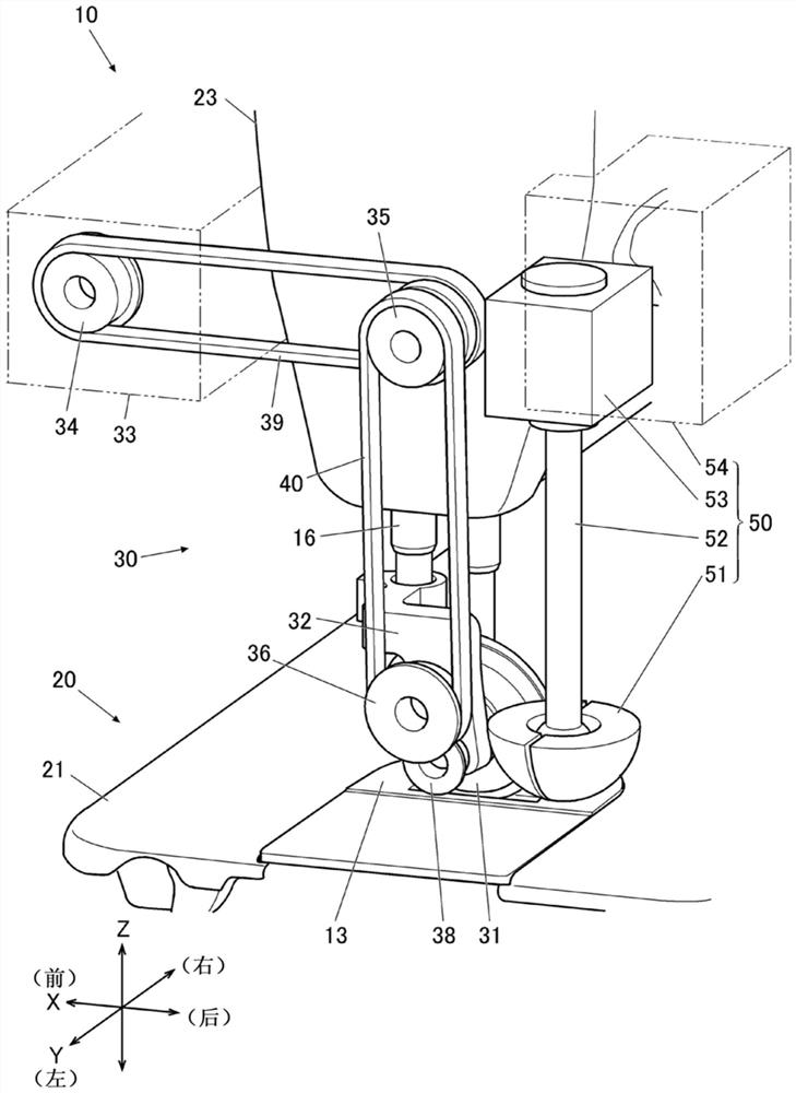
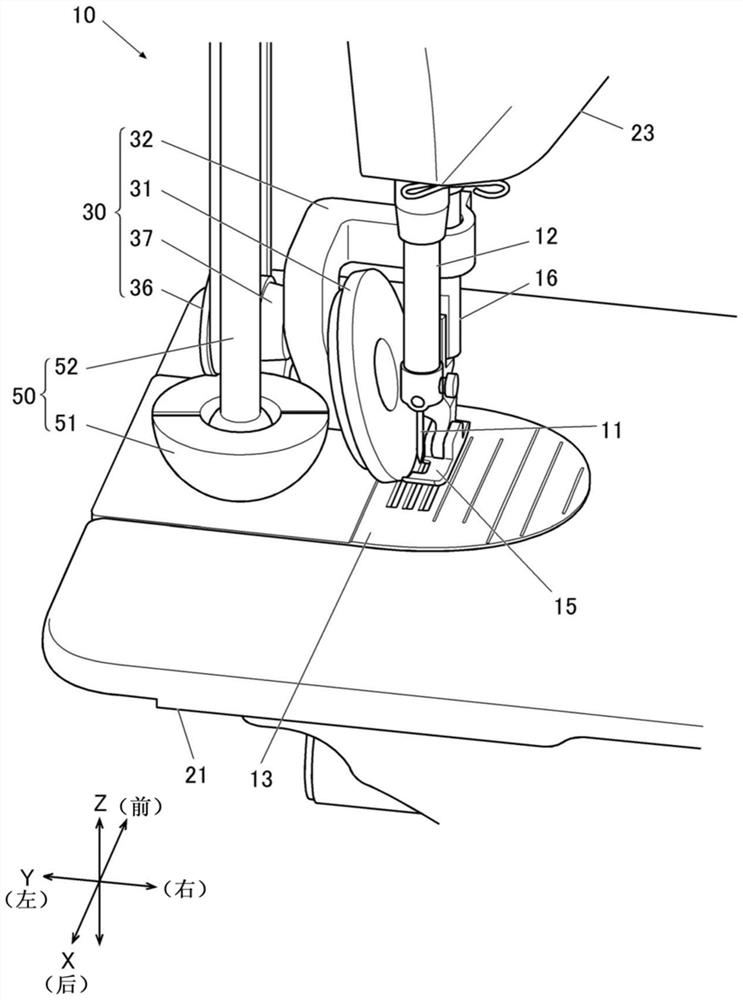
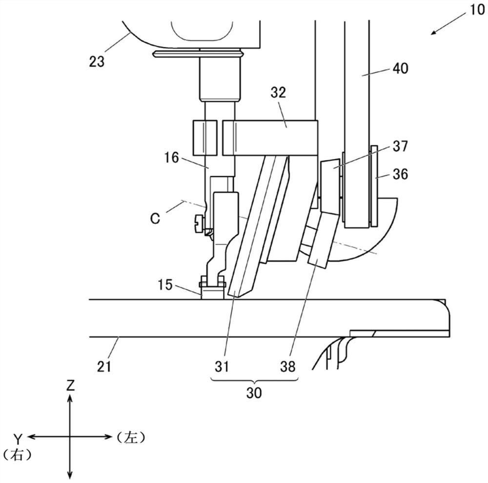
[0064] Below, based on Figure 1 to Figure 7 , the sewing machine 10 as an embodiment of the present invention will be described.

[0065] figure 1 It is a perspective view omitting a part of the structure of the sewing machine 10, figure 2 It is an oblique view viewed from another direction.

[0066] The above-mentioned sewing machine 10 is equipped with: a needle bar 12, which holds the sewing needle 11 at the lower end; a needle bar vertical movement mechanism (not shown), which moves the needle bar 12 up and down; The upper thread of the needle 11 is caught and entangled with the lower thread; the main feed mechanism (not shown in the figure) makes the feed teeth enter and exit from the opening of the needle plate 13, and advances the sewing object in a predetermined straight direction. Give; the first feeding mechanism 30, which is adjacent to the needle drop position of the needle plate 13, that is, the needle hole, car...


PUM


Abstract

The present invention performs sewing along curves better. Equipped with: a first feed mechanism (30), which feeds the sewing object through rollers (31) arranged in an inclined state at the adjacent position of the needle drop position; a second feed mechanism (50), It is arranged on the upstream side of the feeding direction relative to the first feeding mechanism, and is equipped with a feed body (51) that contacts the object to be sewn at a position eccentric from the rotation center, and performs sewing along an arc around the rotation center. The feeding of the object; the control device (90), which controls the driving source (33) of the first feeding mechanism and the driving source (53) of the second feeding mechanism; The direction intersecting the feed direction of the object at the needle drop position detects the position of the side end of the object, and the control device and the side end of the object detected by the side end detection part The rotation speed of the driving source of the second feeding mechanism is controlled correspondingly to the position of the portion.

Description

technical field [0001] The present invention relates to a sewing machine suitable for sewing along curves. Background technique [0002] For example, when sewing a to-be-sewn object along a curve, currently, the operator presses the to-be-sewn object with his left hand, slides his right hand, and rotates around the left hand. [0003] In the case of this sewing, in order to sew along the locus of the target curve, skilled skills are required, and there is a problem that only skilled workers can sew. [0004] In view of the above problems, there has been proposed a sewing machine including a roller feed unit that cooperates with the feed teeth to feed a to-be-sewn object at a position adjacent to the needle drop position. [0005] In this sewing machine, the rotation axis of the roller in the roller feeding section is inclined relative to the horizontal direction, and the roller is rotationally driven by a motor, so that the object to be sewn can be conveyed along the arc sh...

Claims


Application Information

Patent Timeline
Patent Type & Authority Patents(China)
IPC IPC(8): D05B27/18D05B69/10
CPCD05B27/18D05B69/10D05D2305/32
Inventor 横山正
Owner JUKI CORP
Learn More