
Automobile rear side window area reinforcing structure and automobile

A technology for strengthening structure and window area, applied in the directions of superstructure, superstructure sub-assemblies, vehicle components, etc., can solve the problems of difficult design and complex structure of the rear side window area, and achieve the effect of improving rigidity

Active Publication Date: 2016-12-21
CHONGQING CHANGAN AUTOMOBILE CO LTD
View PDF6 Cites 1 Cited by
  • Summary
  • Abstract
  • Description
  • Claims
  • Application Information

AI Technical Summary

Problems solved by technology

[0002] Existing seven-seater family or commercial vehicles such as MPV and SUV are equipped with rear side windows on both sides of the rear, and the rear side windows are located between the C-pillar and D-pillar. The window area is equipped with a rear side window reinforcement structure. The main function of the rear side window reinforcement structure is to enhance the rigidity of the rear side window area. However, the structure of the rear side window area is relatively complicated and the design is difficult. How to maximize the weight of the vehicle? It has always been a difficult point to improve the rigidity of the rear side window area, suppress the vibration transmission of the back door and the vibration transmission of the rear wheel

Method used


Image

  • Automobile rear side window area reinforcing structure and automobile
  • Automobile rear side window area reinforcing structure and automobile
  • Automobile rear side window area reinforcing structure and automobile

Examples


Embodiment Construction

[0022] The present invention will be further described below in conjunction with accompanying drawing.

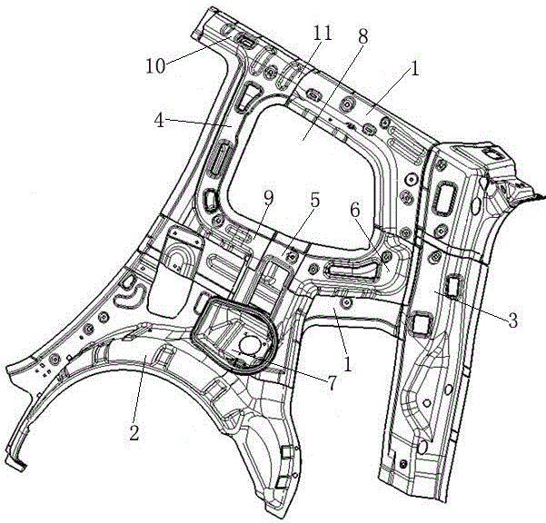
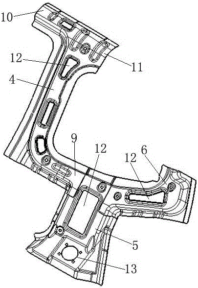
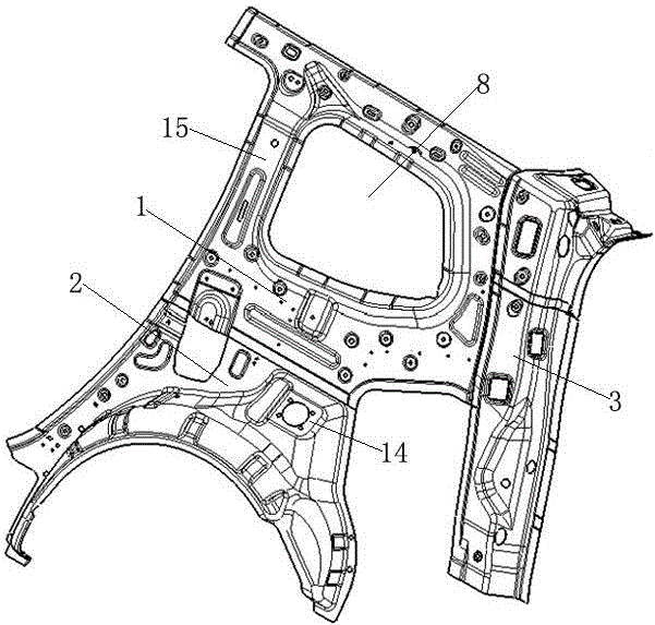
[0023] like figure 1 The rear side window area reinforcement structure of a car shown includes a rear side wall inner panel 1, a rear wheel house outer panel 2 lapped on the lower side of the rear side wall inner panel 1, and a rear wheel house outer panel 2 lapped behind the rear side wall inner panel 1. The side D-pillar reinforcement 3, the upper part of the rear side wall inner panel 1 has the rear side window 8, the rear side wall inner panel 1 is formed with the C-pillar inner panel 15 on the front side of the rear side window 8, the rear side wall inner panel 1 The face facing the outside of the car is lapped like figure 2 As shown in the reinforcement assembly, the reinforcement assembly forms a cavity reinforcement structure on the rear side wall inner panel 1, and the reinforcement assembly includes a first vertical extension section lapped on the C-pillar inner...


PUM


Abstract

The invention relates to an automobile rear side window area reinforcing structure and an automobile. The automobile rear side window area reinforcing structure comprises a rear side wall inner plate, a rear wheel cover outer plate and a D pillar reinforcing part, wherein a rear side window is arranged at the upper part of the rear side wall inner plate, a C pillar inner plate is formed on the rear side wall inner plate and located on the front side of the rear side window, a reinforcing part assembly is overlapped on the surface, facing the exterior of the automobile, of the rear side wall inner plate, and a cavity reinforcing structure is formed in reinforcing part assembly on the rear side wall inner plate, the reinforcing part assembly comprises a first vertical extending section overlapped on the C pillar inner plate, a transverse extending section extending backwards from the lower end part of the first vertical extending section as well as a second vertical extending section extending downwards from the transverse extending section, the transverse extending section is arranged along the lower edge of the rear side window, the rear end part of the transverse extending section is overlapped on the D pillar reinforcing part, and the lower end part of the second vertical extending section is overlapped on an outer plate of the rear wheel cover outer plate. Excessive increasing of dead weight of the automobile is avoided while the rigidity of the rear side window area is improved and vibration transmission of back doors and vibration transmission of rear wheels are inhibited.

Description

technical field [0001] The invention relates to automobiles, in particular to an automobile rear side window area reinforcement structure and the automobile. Background technique [0002] Existing seven-seater family or commercial vehicles such as MPV and SUV are equipped with rear side windows on both sides of the rear, and the rear side windows are located between the C-pillar and D-pillar. The window area is equipped with a rear side window reinforcement structure. The main function of the rear side window reinforcement structure is to enhance the rigidity of the rear side window area. However, the structure of the rear side window area is relatively complicated and the design is difficult. How to maximize the weight of the vehicle? It has always been a difficult point to improve the rigidity of the rear side window area, suppress the vibration transmission of the back door and the vibration transmission of the rear wheel. Contents of the invention [0003] The object ...

Claims


Application Information

Patent Timeline
IPC IPC(8): B62D25/02B60J5/04
CPCB62D25/02B60J5/042
Inventor 高飞任涛
Owner CHONGQING CHANGAN AUTOMOBILE CO LTD
Learn More