Flying equipment capable of vertical take-off

A technology for flying equipment and rotors, which is applied in the field of flying equipment and can solve problems such as changing angular momentum

Active Publication Date: 2020-03-27
AIRBUS DEFENCE & SPACE
View PDF7 Cites 0 Cited by
  • Summary
  • Abstract
  • Description
  • Claims
  • Application Information

AI Technical Summary

Problems solved by technology

[0007] However, this flying device has the disadvantage that as the size of the flying device increases, it becomes more and more difficult to change the angular momentum sufficiently

Method used


Image

  • Flying equipment capable of vertical take-off
  • Flying equipment capable of vertical take-off
  • Flying equipment capable of vertical take-off

Examples


Embodiment Construction

[0036] The following detailed description refers to the accompanying drawings that, for purposes of illustration, show specific details and embodiments in which the invention can be practiced.

[0037] The word "exemplarily" is used herein in the sense "as an example, situation, or illustration." Every embodiment or configuration described herein as "exemplary" is not necessarily designed to be preferred or advantageous over other embodiments or configurations.

[0038] In the following detailed description, reference is made to the accompanying drawings which form a part hereof and in which are shown, for purposes of illustration, specific embodiments in which the invention can be practiced. In this regard, directional terms such as "upper", "lower", "front", "rear", "further forward", "further rearward", etc. are used with reference to the orientation of the figure(s) being described. Because components of the embodiments can be positioned in a number of different orientati...


PUM


Abstract

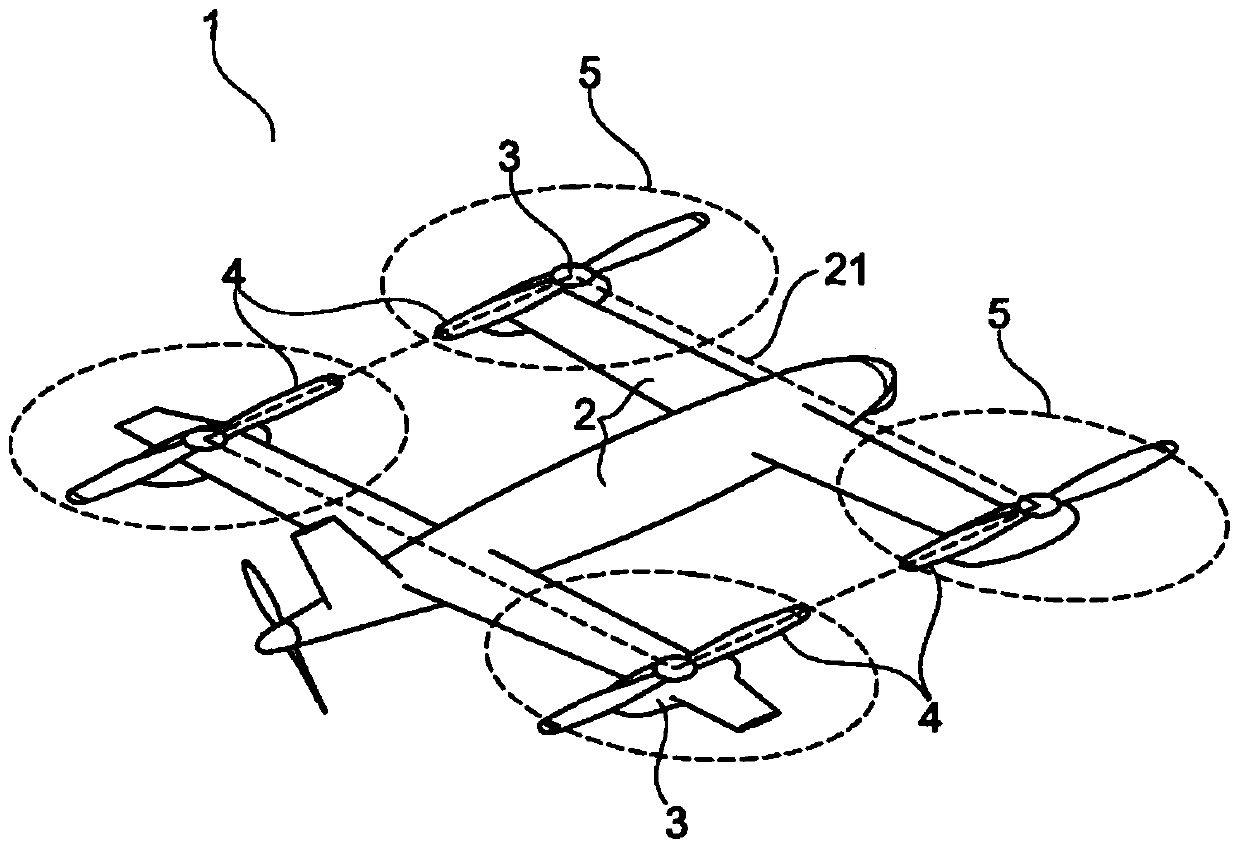
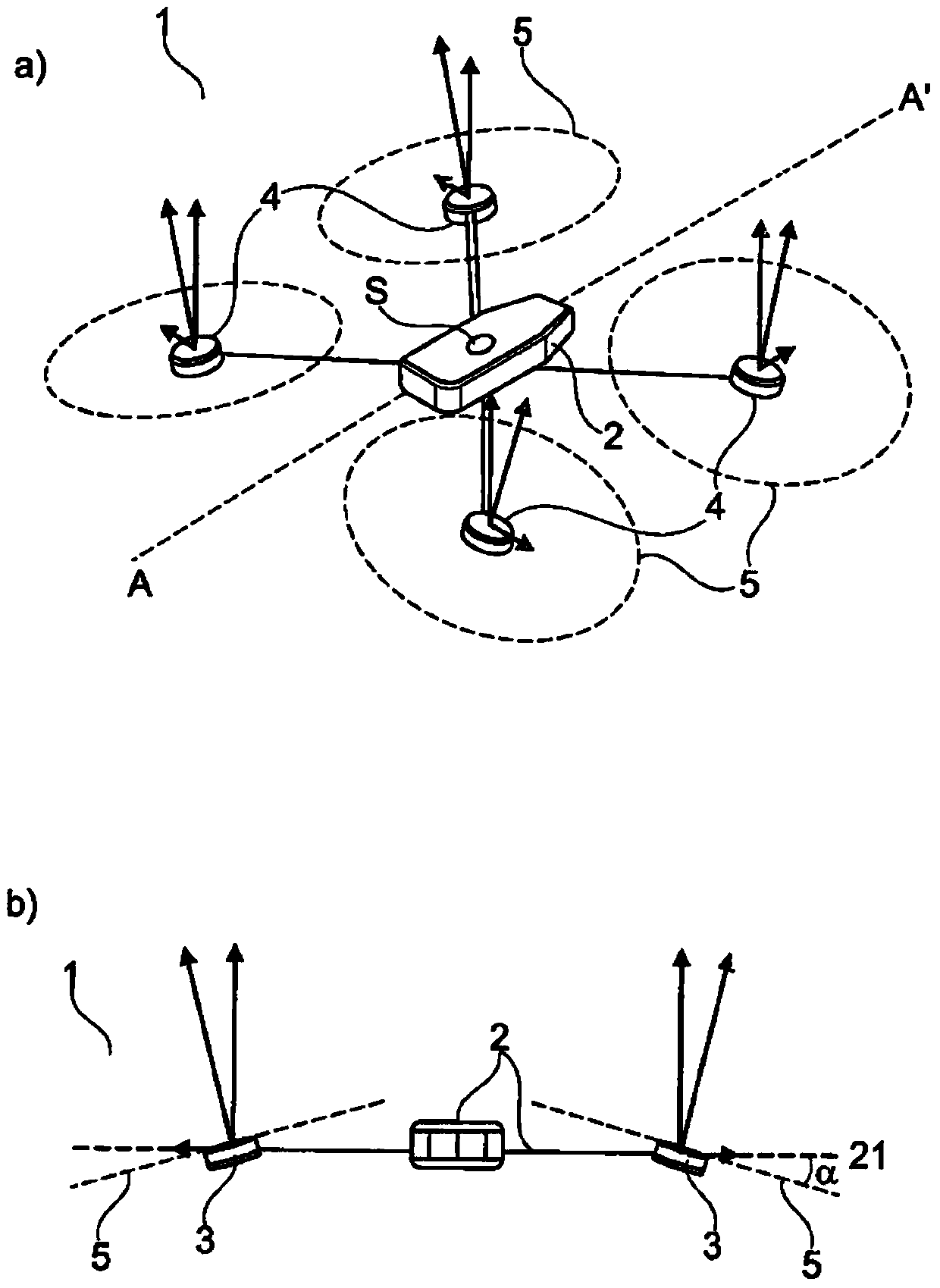
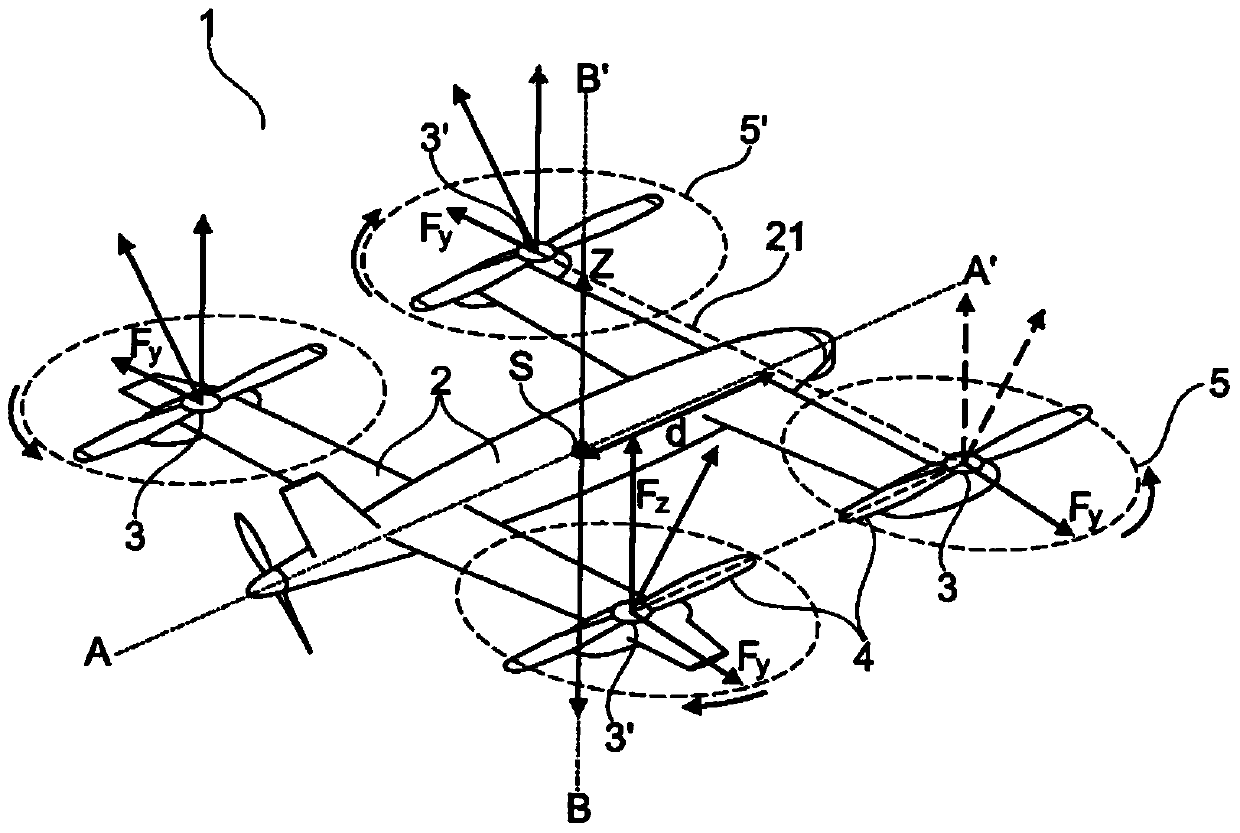
The invention proposes an aircraft with a support structure and at least four elevating rotors. Each of the elevating rotors is fixed to the load-bearing structure and has at least one propeller. The elevating rotor is designed such that the plane of rotation in which at least one propeller of the elevating rotor rotates is inclined relative to the plane unfolded by the supporting structure.

Description

technical field [0001] The present invention relates to a flying device capable of vertical take-off, for example similar to a quadcopter. Background technique [0002] For many applications it is desirable to provide an aircraft that can be launched from a minimally small area so that, for example, a dedicated large-area airfield is not required. In addition, for specific application purposes, flying devices are required that are flexible and can be maneuvered precisely, and that are preferably capable of hovering immediately and in this case can have a good Hover flight characteristics. [0003] For aerial monitoring and aerial reconnaissance, for example, flying devices are used which are to be able to hover over interesting destinations and to take aerial images, for example. In an alternative application, a vertical take-off flying device could be used to fly into areas that are difficult for humans or other machines to access, for example in the context of disaster r...

Claims


Application Information

Patent Timeline
Patent Type & Authority Patents(China)
IPC IPC(8): B64C27/52B64C27/08
CPCB64C27/52B64U10/20B64U30/20B64U30/297B64C29/00B64C29/0033B64C39/024B64C27/20B64C29/0025B64U10/13B64U2101/30B64U2101/60
Inventor 迈克尔·茹达斯克莱门斯·格拉克托马斯·克劳斯贝特霍尔德·卡赖斯
Owner AIRBUS DEFENCE & SPACE
Why Eureka
Try Eureka