
Hydraulic pile driver for highway guardrails

A technology for road guardrails and piling machines, which is applied in sheet pile walls, buildings, and foundation structure engineering, etc. It can solve the problems of low drop hammer precision, lower construction quality, and low automation, and achieve high piling accuracy, quality assurance, and automation. high degree of effect

Active Publication Date: 2016-11-23
山东八达国际工程机械有限公司
View PDF5 Cites 9 Cited by
  • Summary
  • Abstract
  • Description
  • Claims
  • Application Information

AI Technical Summary

Problems solved by technology

[0003] The working efficiency of these machines is mainly reflected in the movement state of the hammer drop process. The free fall state is the highest efficiency limit. Due to the light chassis, the pile driver generates a large vibration when the drop hammer hits the pile body, and the precision of the drop hammer is low, which leads to construction failure. decline in quality
In addition, the existing pile drivers still have the problem of low degree of automation. Looking at the development of construction machinery at home and abroad, for road construction machinery, it is the development trend to increase the degree of automation, reduce the labor intensity of workers, and improve the construction quality.

Method used


Image

  • Hydraulic pile driver for highway guardrails
  • Hydraulic pile driver for highway guardrails
  • Hydraulic pile driver for highway guardrails

Examples


Embodiment Construction

[0038] The present invention will be further explained below in conjunction with the accompanying drawings.

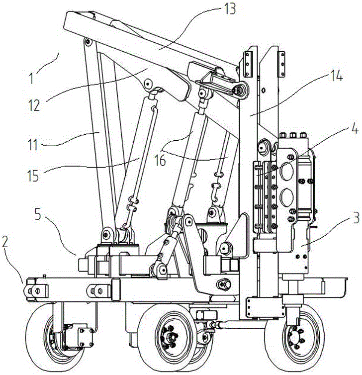
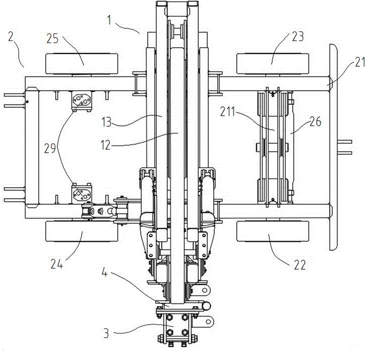
[0039] The road guardrail hydraulic pile driver of the present invention comprises a pile frame 1, a four-wheel chassis 2 for supporting the pile frame 1, a hydraulic hammer 3, a hinge type carriage 4 that drives the hydraulic hammer 3 to slide on the pile frame 1 and is arranged on The four-wheel chassis 2 is used to drive the telescopic mechanism 5 for adjusting the vertical and horizontal swing of the pile frame 1 in the horizontal plane; Figure 10 , the hydraulic hammer 3 includes a drill rod 31 and a drill cap 32; the telescopic mechanism 5 is provided with a guide rail cylinder ear plate 531, a swing arm cylinder ear plate 532 and a lower guide rail hinge plate 535;

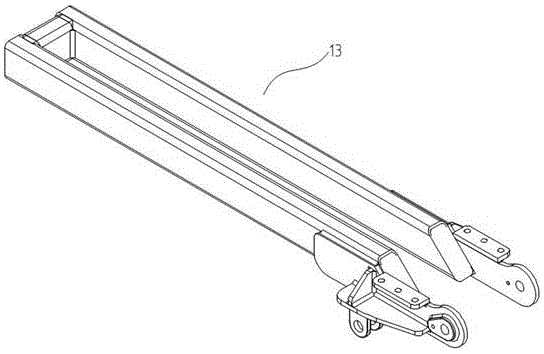
[0040] The pile frame 1 includes a connecting plate 11, a swing arm 12, an upper guide rail 13, a lower guide rail 14, a swing arm cylinder 15 and a guide rail cylinder 16;

[0041] One end of the...


PUM


Abstract

The invention relates to a hydraulic pile driver for highway guardrails. The hydraulic pile driver for the high-way guardrails comprises a pile frame, a four-wheel chassis for supporting the pile frame, a hydraulic hammer, a hinge type sliding frame driving the hydraulic hammer to slide on the pile frame and a stretching and retracting mechanism which is arranged on the four-wheel chassis and used for driving the pile frame to longitudinally and transversely swing for adjustment on the horizontal plane. The pile frame comprises a connecting plate, a swing arm, an upper guide rail, a lower guide rail, a swing arm oil cylinder and a guide rail oil cylinder. One end of the swing arm is hinged to the upper end of the connecting plate, and the other end of the swing arm is hinged to the hinge type sliding frame. The upper end of the lower guide rail is hinged to the upper guide rail. The lower end of the lower guide rail is hinged to the stretching and retracting mechanism. The hinge type sliding frame is matched with the lower guide rail in a matched manner. The upper end of the swing arm oil cylinder is hinged to the middle of the swing arm. The lower end of the swing arm oil cylinder and the lower end of the connecting plate are hinged to the stretching and retracting mechanism together. The upper end of the guide rail oil cylinder is hinged to the upper guide rail, the lower end of the guide rail oil cylinder is hinged to the stretching and retracting mechanism, and therefore the upper guide rail and the lower guide rail are driven by the guide rail oil cylinder to ascend and descend.

Description

technical field [0001] The invention relates to the field of pile driver equipment, in particular to a highway guardrail hydraulic pile driver. Background technique [0002] According to the construction situation in our country, the time left for guardrail construction in the same period of expressway construction is generally very short, and the construction period is tight, so the piling machine is required to have higher operating efficiency. The existing domestic highway guardrail piling machines are mainly of the drop hammer type, which can be divided into two types: vehicle-mounted and self-propelled. The vehicle-mounted pile driver is represented by the Isuzu chassis pile driver produced by Shenyang Modern Transportation Facilities Co., Ltd. Self-propelled hydraulic pile drivers mainly include: YDBZ-180 self-propelled hydraulic pile drivers produced by Xuzhou Bada Highway Engineering Machinery Facility Manufacturing Factory, and self-propelled pile drivers produced ...

Claims


Application Information

Patent Timeline
IPC IPC(8): E02D7/10E02D7/16
CPCE02D7/10E02D7/165
Inventor 于瑞杰陈建军
Owner 山东八达国际工程机械有限公司
Learn More