A butterfly grinding disc and its process for grinding the end face and annular groove of valve body parts

A technology of grinding discs and annular grooves, applied in machine tools suitable for grinding workpiece planes, wheels with flexible working parts, grinding machines, etc., can solve the problems of inability to grind, difficult for workers to operate, and reduce assembly accuracy, etc. To achieve the effect of convenient worker operation, simple grinding process and high grinding efficiency

Active Publication Date: 2018-08-03
丹棱县逸兴机械零部件有限公司
View PDF9 Cites 0 Cited by
  • Summary
  • Abstract
  • Description
  • Claims
  • Application Information

AI Technical Summary

Problems solved by technology

[0002] The hydraulic system is composed of various valve bodies, pipelines, oil cylinders and other hydraulic components, among which the valve body and oil cylinder play a very important role. There are annular grooves processed in the valve body and the cylinder barrel, and multiple ring grooves are installed in the annular grooves to prevent For the seal ring with hydraulic oil leakage, if the inner surface finish of the annular groove is poor, it will cause friction or extrusion damage to the seal ring during use, which will reduce the service life of the seal ring and eventually cause a gap between the seal ring and the annular groove. There is a phenomenon of hydraulic oil leakage; in addition, the end face of the valve body and the cylinder barrel is mainly used to cooperate with the end cover. If the end surface finish is poor, there will be a gap during the assembly process with the end cover, which reduces the assembly accuracy and shortens the entire assembly. service life
[0003] In order to solve the above problems, grinding wheels are usually used to grind the annular groove and the end face. However, the use of the grinding wheel is not flexible, and it is difficult to extend into the annular groove, which brings difficulties to the worker's operation; "Dead angle" or rounded corner grinding, so there is an urgent need for a grinding device and method to finely grind the annular groove and end face on the valve body or cylinder

Method used


Image

  • A butterfly grinding disc and its process for grinding the end face and annular groove of valve body parts
  • A butterfly grinding disc and its process for grinding the end face and annular groove of valve body parts
  • A butterfly grinding disc and its process for grinding the end face and annular groove of valve body parts

Examples


Embodiment 1

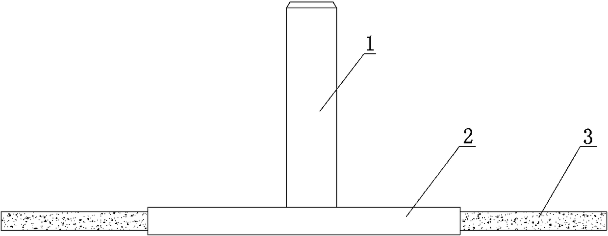
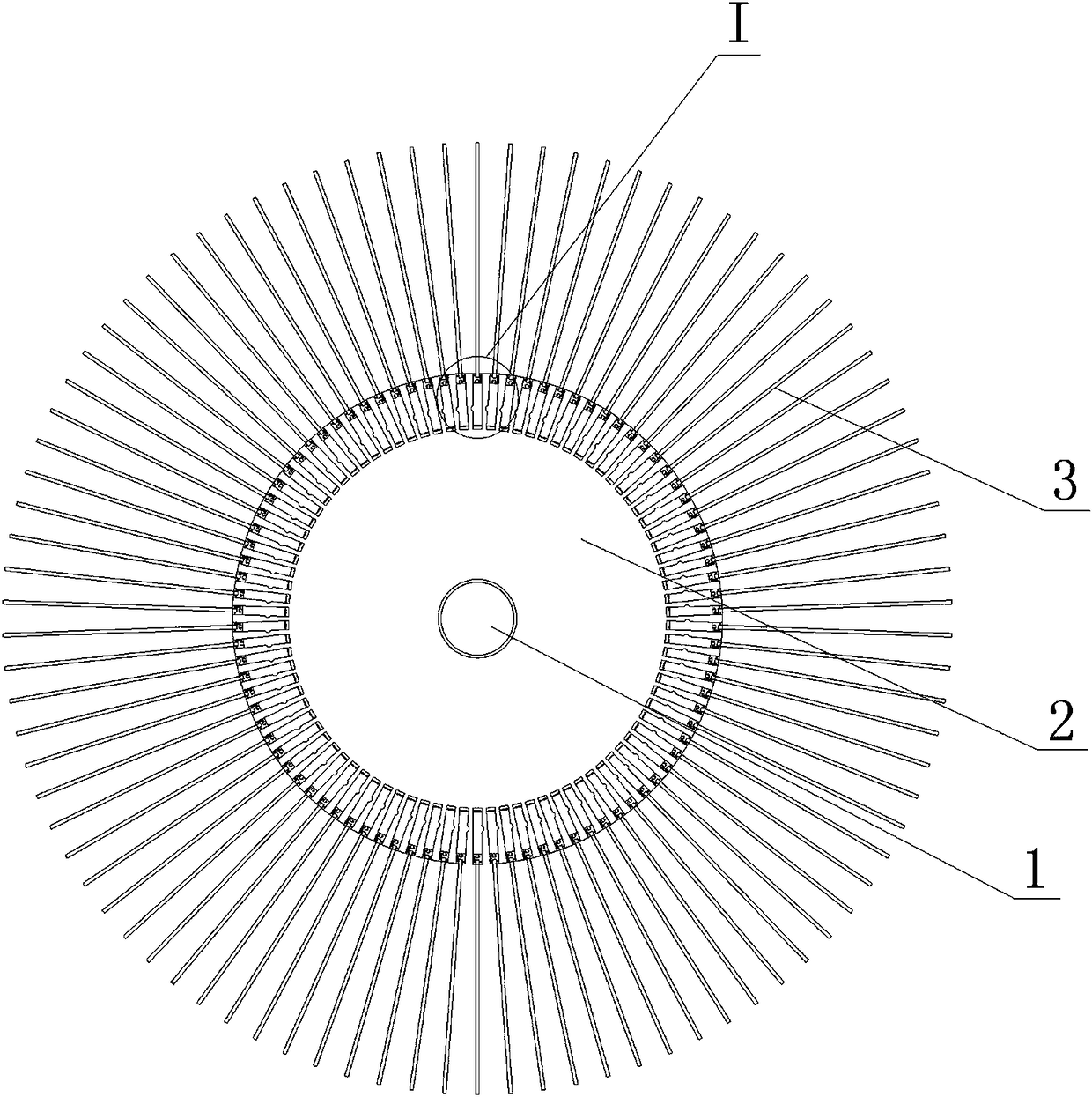
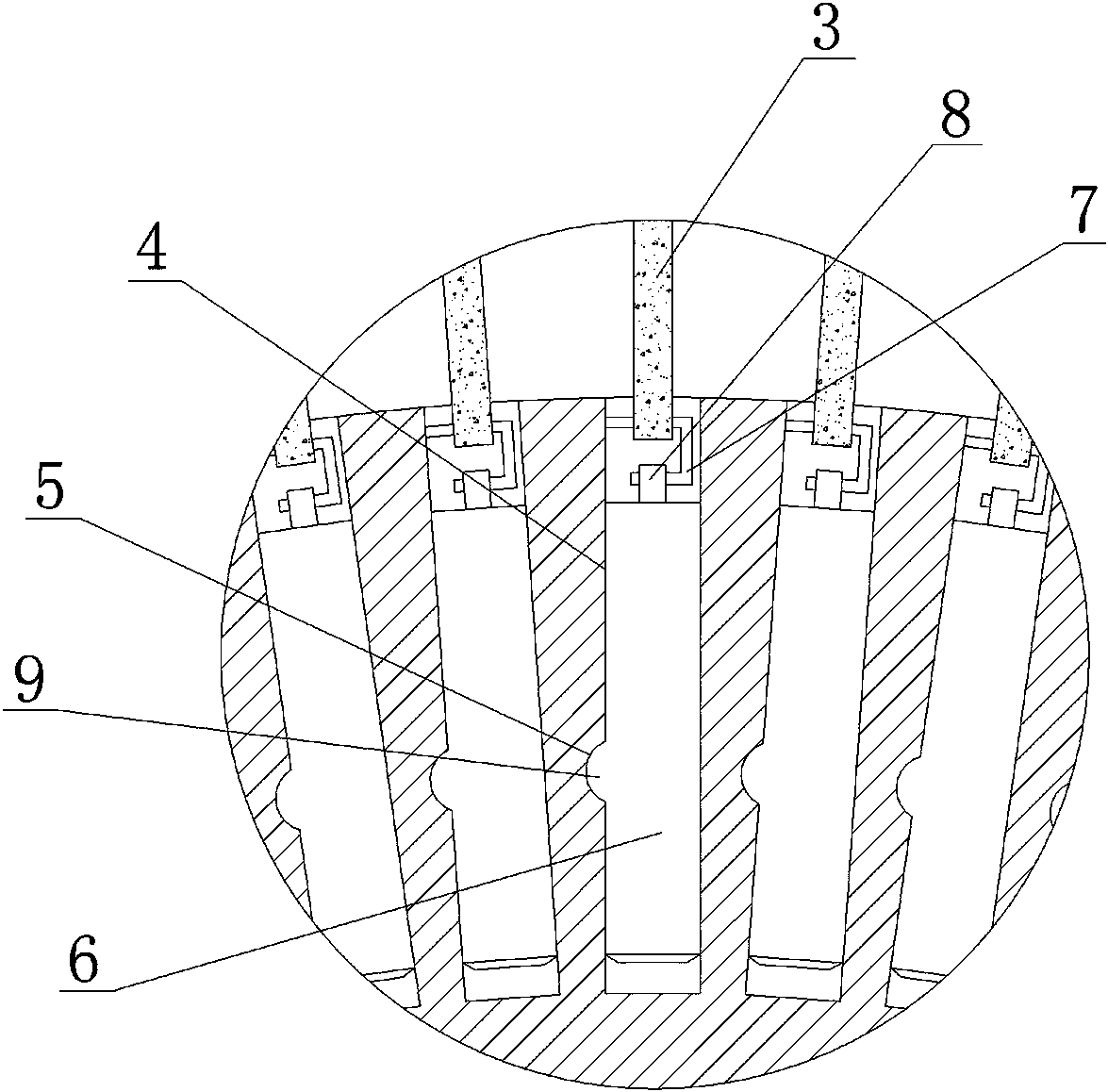
[0023] Embodiment one: if Figure 1~3 As shown, a butterfly-shaped grinding disc, which includes a rotating shaft 1, a plastic disc 2, a strip-shaped abrasive cloth 3 and a strip-shaped abrasive cloth fixing structure, the described rotating shaft 1 is fixed on the top surface of the plastic disc 2, and the described plastic disc 2 It is circular, rectangular or square. In this embodiment, the plastic disc 2 is circular. There are a plurality of grooves 4 evenly on the plastic disc 2 and along the edge of the plastic disc 2. There are arcs on the side walls of the grooves 4. shaped groove 5, the strip-shaped abrasive cloth fixing structure is arranged in the groove 4, the strip-shaped abrasive cloth fixing structure is composed of a plastic cylinder 6, a bent plate 7, a boss 8 and an arc-shaped block 9, and the arc-shaped block 9 is also It is a plastic part and is integrated with the plastic cylinder 6. The arc-shaped block 9 is arranged on the side wall of the plastic cylind...

Embodiment 2

[0032] Embodiment 2: The difference between this embodiment and Embodiment 1 is that the process of grinding the end face and the annular groove of the valve body parts with the butterfly grinding disc includes the following steps:

[0033] S1, such as Figure 4 As shown, for the tooling of the valve body 10 to be polished, the outer wall of the valve body 10 is clamped by the three-jaw chuck, and the grinding surface 11 is exposed to the outside, thereby realizing the tooling of the valve body;

[0034] S2. Rotate the three-jaw chuck at a speed of 58r / min to make the valve body 10 rotate around its own axis;

[0035] S3. Connect the rotating shaft 1 of the butterfly-shaped grinding disc to the output shaft of the grinding gun, start the grinding gun, and the grinding gun drives the plastic disc 2 to rotate at 1350r / min, and the direction of rotation is opposite to that of the three-jaw chuck;

[0036] S4. For fine grinding of the annular groove of the valve body, the plastic...

Embodiment 3

[0038] Embodiment three: the difference between this embodiment and embodiment one is that the process of grinding the end face and annular groove of the valve body parts with the butterfly grinding disc includes the following steps:

[0039] S1, such as Figure 4 As shown, for the tooling of the valve body 10 to be polished, the outer wall of the valve body 10 is clamped by the three-jaw chuck, and the grinding surface 11 is exposed outside, thereby realizing the tooling of the valve body;

[0040] S2. Rotate the three-jaw chuck at a speed of 60r / min to make the valve body 10 rotate around its own axis;

[0041] S3. Connect the rotating shaft 1 of the butterfly-shaped grinding disc to the output shaft of the grinding gun, start the grinding gun, and the grinding gun drives the plastic disc 2 to rotate at 1500r / min, and the direction of rotation is opposite to that of the three-jaw chuck;

[0042]S4. For fine grinding of the annular groove of the valve body, the plastic disk ...


PUM


Abstract

The invention discloses a disc-shaped polishing disc. The disc-shaped polishing disc comprises a rotary shaft (1), a plastic disc (2), strip-shaped abrasive cloth (3) and strip-shaped abrasive cloth fixing structures. Multiple grooves (4) are evenly formed in the rim of the plastic disc (2). An arc-shaped groove (5) is formed in the side wall of each groove (4). Each strip-shaped abrasive cloth fixing structure is composed of a plastic column body (6), a bent plate (7), a boss (8) and an arc-shaped block (9). Each arc-shaped block (9) is arranged on the side wall of the corresponding plastic column body (6) and matched with the corresponding arc-shaped groove (5). One end of each bent plate (7) is arranged in the corresponding boss (8) in a penetrating manner. The other end of each bent plate (7) is in tight contact with the side wall of the corresponding groove (4). The lower end of each strip-shaped abrasive cloth (3) is fixed to the corresponding bent plate (7). The disc-shaped polishing disc has the beneficial effects that the strip-shaped abrasive cloth can be disassembled and assembled quickly, the polishing process is simple, the polishing efficiency is high, the polishing precision is high, and operation is facilitated for workers.

Description

technical field [0001] The invention relates to the technical field of grinding an annular groove and an end surface of a valve body or an oil cylinder barrel, in particular to a butterfly grinding disc and a process for grinding the end surface and an annular groove of a valve body part. Background technique [0002] The hydraulic system is composed of various valve bodies, pipelines, oil cylinders and other hydraulic components, among which the valve body and oil cylinder play a very important role. There are annular grooves processed in the valve body and the cylinder barrel, and multiple ring grooves are installed in the annular grooves to prevent For the seal ring with hydraulic oil leakage, if the inner surface finish of the annular groove is poor, it will cause friction or extrusion damage to the seal ring during use, which will reduce the service life of the seal ring and eventually cause a gap between the seal ring and the annular groove. There is a phenomenon of hy...

Claims


Application Information

Patent Timeline
Patent Type & Authority Patents(China)
IPC IPC(8): B24D13/04B24B7/16B24B19/02
CPCB24B7/16B24B19/02B24D13/04
Inventor 张治华
Owner 丹棱县逸兴机械零部件有限公司
Why Eureka
Try Eureka