
Power Station Grounding Grid

A technology for grounding grids and power stations, applied in the electrical field, can solve problems such as increased noise, ground current leakage, insulation breakdown, etc., and achieve the effects of reducing ground current, improving safety, and reducing flow

Active Publication Date: 2018-03-27
STATE NUCLEAR ELECTRIC POWER PLANNING DESIGN & RES INST CO LTD +1
View PDF5 Cites 2 Cited by
  • Summary
  • Abstract
  • Description
  • Claims
  • Application Information

AI Technical Summary

Problems solved by technology

[0005] Due to the different composition materials of the grounding grids of each power station, the grounding effect of the grounding grids of each power station is also different, which leads to more ground current leakage through the grounding grid of the power station with better grounding effect
At this time, the ground current on the power grid will flow through the main transformer winding of the power station with better grounding effect through the overhead line, causing the DC bias of the main transformer and increasing the noise. Long-term operation will affect the insulation of the transformer winding. Wear accidents, which in turn lead to greater safety hazards in the power station with better grounding effect

Method used


Image

  • Power Station Grounding Grid
  • Power Station Grounding Grid
  • Power Station Grounding Grid

Examples


Embodiment Construction

[0034] Reference will now be made in detail to the exemplary embodiments, examples of which are illustrated in the accompanying drawings. When the following description refers to the accompanying drawings, the same numerals in different drawings refer to the same or similar elements unless otherwise indicated. The implementations described in the following exemplary examples do not represent all implementations consistent with the present disclosure. Rather, they are merely examples of apparatuses and methods consistent with aspects of the present disclosure as recited in the appended claims.

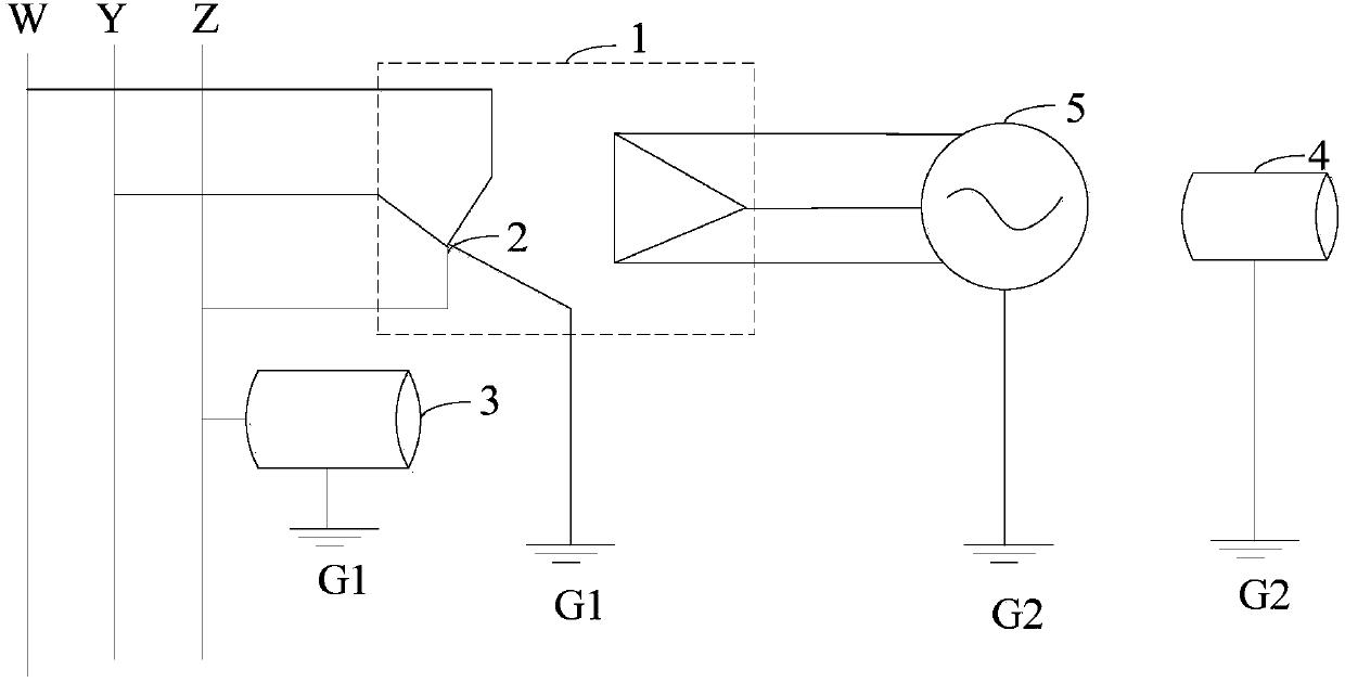
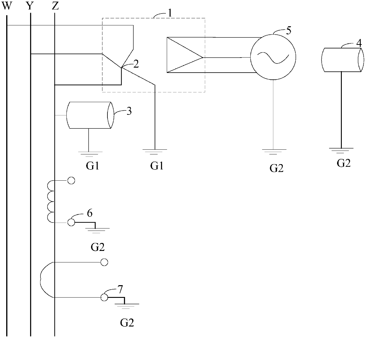
[0035] Figure 1A is a schematic diagram of a power station grounding grid G ​​shown according to some exemplary embodiments, as shown in Figure 1A As shown, the power station grounding grid G ​​may include a power grid side grounding grid G1 and a power station side grounding grid G2.

[0036] The grounding grid G ​​of the power station can be used to discharge the ground current exi...


PUM


Abstract

The invention discloses a power station grounding grid and belongs to the electric field. The power station grounding grid includes a grid-side grounding grid and a power station-side grounding grid; the grid-side grounding grid is electrically connected with the grounding point of the neutral point of a step-up main transformer; the grid-side grounding grid is electrically connected with the grounding point of first equipment; the first equipment includes equipment directly connected with a power grid; the power station-side grounding grid is electrically connected with the grounding point of second equipment; the second equipment includes equipment of which the working power source is supplied by a power station; and no electrical connection exists between the grid-side grounding grid and the power station-side grounding grid. With the power station grounding grid adopted, harm to the step-up main transformer of the power station caused by ground current can be reduced, and the security of the power grid and the power station can be improved.

Description

technical field [0001] The present disclosure relates to the electrical field, in particular to a grounding grid of a power station. Background technique [0002] Ground currents are ubiquitous in power grids, such as unbalanced neutral point currents of step-up main transformers, geomagnetic induction currents, and ground currents generated under other circumstances, and ground currents pose a great safety hazard to power stations and power station workers Hidden danger. Therefore, in order to reduce the potential safety hazards caused by the ground current to the power station and the staff of the power station, it is necessary to discharge the ground current. [0003] At present, the ground current leakage is realized by the following method: each power station includes a grounding grid, which has the ability to conduct electricity, and can inject the current connected to the grounding grid into the earth. The grounding point of the neutral point, the grounding point of...

Claims


Application Information

Patent Timeline
Patent Type & Authority Patents(China)
IPC IPC(8): H02B5/01
CPCH02B5/01
Inventor 丁仃郑亚锋王春雨屠学伟卢海彬朱孟强刘华
Owner STATE NUCLEAR ELECTRIC POWER PLANNING DESIGN & RES INST CO LTD
Learn More