Jacquard yarn feeding wheel body

A yarn-feeding wheel and yarn-feeding technology, which is applied in textiles and papermaking, weft knitting, knitting, etc., can solve problems such as inability to feed yarn, troubles, and inelastic structure of smooth silk

Inactive Publication Date: 2016-07-27
陈伯霖
View PDF0 Cites 0 Cited by
  • Summary
  • Abstract
  • Description
  • Claims
  • Application Information

AI Technical Summary

Problems solved by technology

[0003] The above-mentioned ceramic yarn feeding cylinders still have the following shortcomings in actual use, which need to be improved urgently: due to the recent changes in the structure of functional yarns, when performing jacquard weaving, functional yarns are often blended with traditional yarns according to market demand. , or use special functional yarns alone, especially the newly developed smooth yarn (FDY), because the structure of smooth yarn is relatively inelastic and fragile, and its surface is smooth and oily, not only cannot be fed in the traditional way, In addition, during jacquard weaving, the yarn tension changes quite a lot and changes frequently. When the yarn feeding cylinder rotates and feeds the yarn rapidly, the yarn is subjected to the rod-type rotating tangential force of the yarn feeding cylinder. The yarn is broken due to tension, causing the problem that the jacquard yarn cannot be fed smoothly. Therefore, the above-mentioned ceramic yarn feeding drum can not be successfully used in the field of jacquard weaving of functional yarns.
[0004] The above-mentioned ceramic yarn feeding wheel body shows various inconveniences derived from the actual use of the existing yarn feeding wheel body, which makes the product's industrial applicability not high. How to overcome the above problems is a goal that the industry needs to work hard on

Method used


Image

  • Jacquard yarn feeding wheel body
  • Jacquard yarn feeding wheel body
  • Jacquard yarn feeding wheel body

Examples


no. 1 example

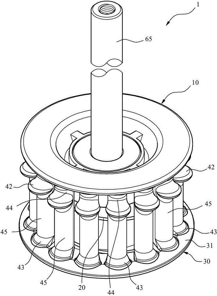
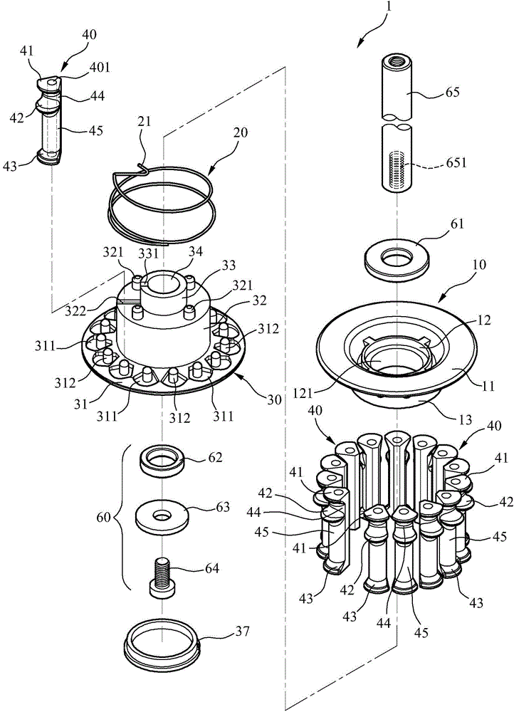
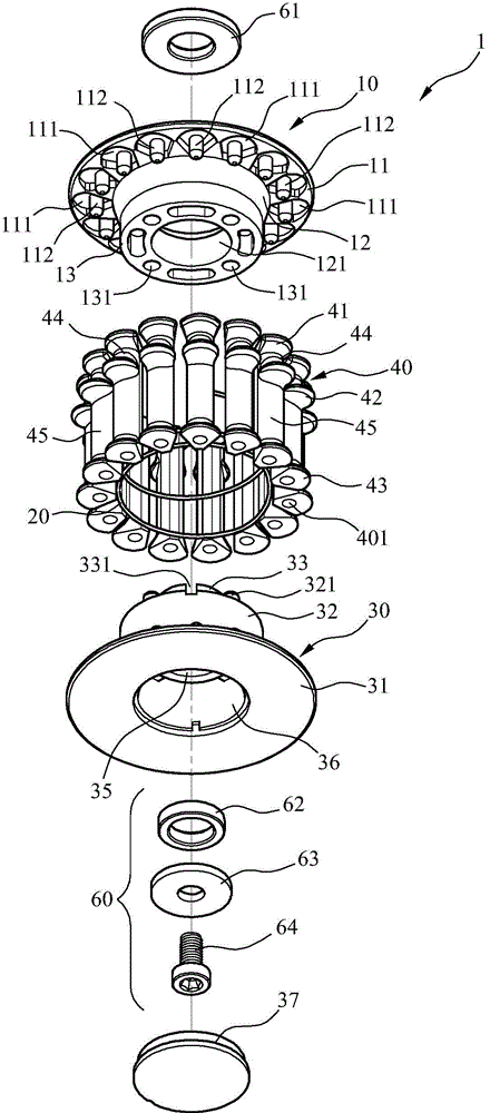
[0049] refer to figure 1 , figure 2 and image 3 , is the first embodiment of the present invention, the jacquard yarn feeding wheel body 1 includes an upper wheel cover 10, a conductive element 20, a lower wheel cover 30, a plurality of ceramic parts 40 and a wheel shaft 65.

[0050] The upper wheel cover 10 includes a ring body of the upper solid rod portion 11 , and a bearing seat 12 with a first through hole 121 is arranged at the center thereof. At image 3 Among them, the upper fixed rod portion 11 of the upper wheel cover 10 is equally spaced and annularly arranged with a plurality of upper embedded rod grooves 111, and the plurality of upper inserted rod grooves 111 are provided with protrusions 112. The first of the upper wheel cover 10 The lower periphery of the through hole 121 includes a bottom ring 13 with a plurality of first locking holes 131 .

[0051] The conductive element 20 is wound into a spring shape, and a conductive elastic hook portion 21 is provi...


PUM


Abstract

The invention provides a jacquard yarn feeding wheel body which comprises an upper wheel cover, a lower wheel cover and a plurality of ceramic parts, wherein the upper wheel cover is provided with an upper rod fixing portion, the center of the upper wheel cover is provided with a bearing block, and the bearing block is provided with a first penetrating hole; the lower wheel cover comprises a lower rod fixing portion, a first step portion, a second step portion, a second penetrating hole and a bearing groove communicated with the second penetrating hole; each ceramic part is provided with an outwards arc portion, each ceramic part is provided with an upper end portion protruding outwards and a middle portion and a lower end portion at a minimum, each ceramic part is divided into a yarn storage segment on the uppermost portion and one or more yarn feeding segments below the corresponding yarn storage segment from top to bottom through the corresponding middle portion, so that the yarn feeding wheel can feed yarn through the friction acting force generated in the yarn feeding process of the corresponding ceramic part, a wheel rubber gasket can be omitted, and the yarn feeding wheel is of a staggered wave-shaped structure, so that yarn feeding can be smooth, manufacturing is convenient, and a fault is not caused easily.

Description

technical field [0001] The present invention relates to a jacquard yarn feeding wheel body; in particular to a ceramic jacquard yarn feeding wheel body made of two or more yarn feeding sections, the upper section is a buffer yarn storage section, the lower section is a yarn feeding section, when winding yarn, The upper buffer yarn storage section first winds a few turns to store the yarn, and then transfers to the lower yarn feeding section through the yarn splitting rod, and wraps around the lower yarn feeding section for a few more turns of the yarn feeding amount, and then carries out the subsequent yarn feeding or jacquard yarn feeding operation , after increasing the frictional force between the yarn and the ceramic wheel, there will be no slippage when feeding the yarn, and then the formal yarn feeding or jacquard yarn feeding, so that any traditional yarn or functional yarn can be mixed smoothly and jacquard at the same time Yarn feeding or jacquard yarn feeding separat...

Claims


Application Information

Patent Timeline
IPC IPC(8): D04B15/38
Inventor 陈伯霖
Owner 陈伯霖
Why Eureka
Try Eureka