
Automatic-locating bolt tightening machine

A technology for tightening machines and bolts, used in metal processing, metal processing equipment, manufacturing tools, etc., can solve problems such as difficulty in bolt operation, and achieve the effect of high degree of automation, high efficiency and high safety factor

Inactive Publication Date: 2016-06-15
佛山市炜宏金属制品有限公司
View PDF10 Cites 7 Cited by
  • Summary
  • Abstract
  • Description
  • Claims
  • Application Information

AI Technical Summary

Problems solved by technology

[0007] The purpose of the present invention is to solve the problem of difficult operation during the screwing process of the bolts, and provide an automatic positioning bolt tightening machine, which can automatically find the threaded through holes on the carrier when the tightening joint is tightened, and screw the bolts in

Method used


Image

  • Automatic-locating bolt tightening machine
  • Automatic-locating bolt tightening machine
  • Automatic-locating bolt tightening machine

Examples


Embodiment Construction

[0037] The present invention will be further described below in conjunction with the accompanying drawings.

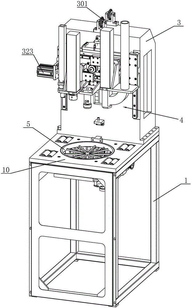
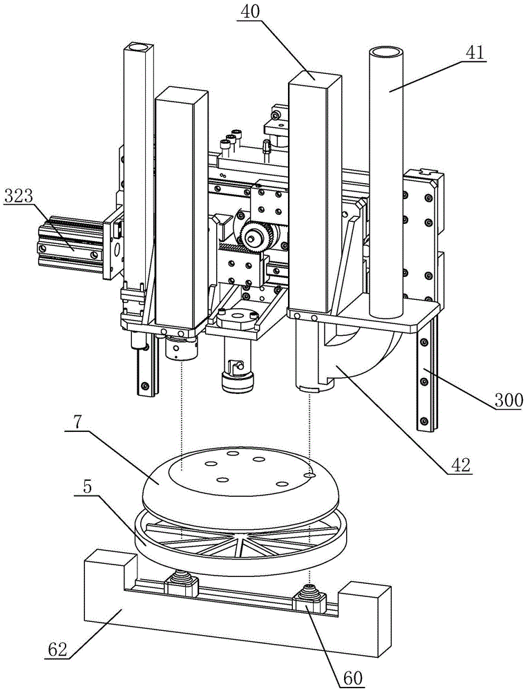
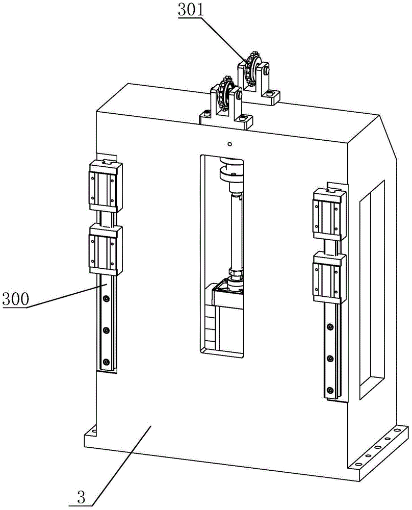
[0038] like Figures 1 to 11 The shown automatic positioning bolt tightening machine includes a base frame 1, a support 3, a laser docking device and a tightening device 4, the tightening device 4 is arranged in front of the support, the top of the base frame 1 is a loading panel 10, and the support 3 is fixed on the upper surface of the loading panel 10, and a horizontal displacement mechanism and a longitudinal displacement mechanism are also provided between the support 3 and the tightening device 4.

[0039] Horizontal shift mechanism: such as Figure 5 As shown, it includes a transverse slide rail 320, a fixed plate 321 and a transverse driving device 323 that controls the movement of the fixed plate. The transverse drive device 323 is fixed on the surface of the base plate 310 or the support 3, and the fixed plate 321 is slidably connected with the transverse sl...


PUM


Abstract

The invention discloses an automatic-locating bolt tightening machine. The automatic-locating bolt tightening machine comprises a laser abutting device, a loading device, a horizontal displacement mechanism, a longitudinal displacement mechanism and an objective table. A tightening joint can rapidly find a threaded through hole on a carrier by the laser abutting device, the loading device is used for mounting a bolt on the tightening joint to achieve rapid and automatic bolt mounting process, multiple bolts can be tightened each time, the efficiency is high, the operation is safe and reliable and the productive forces are greatly emancipated.

Description

technical field [0001] The invention relates to a bolt assembly device, which is an automatic position-seeking bolt tightening machine. Background technique [0002] Since the bolt is tightened with a manual wrench, the efficiency is extremely low, the speed is too slow, and manpower is wasted. [0003] The bolt tightening machine is a machine used to screw the bolts into the carrier. The torque is a set fixed value, and there will be no uneven tightening force like manual tightening. [0004] There is a type of electric wrench (or pneumatic wrench) on the market, which quickly screws the bolt into the carrier through a motor, etc., and can ensure that the torque during tightening is a fixed value, but it has certain disadvantages: [0005] 1. First of all, the weight is heavy, and its working principle is similar to that of an electric drill. It requires a certain amount of physical strength to support and grasp the electric wrench when working, and maintain the angle and ...

Claims


Application Information

Patent Timeline
Patent Type & Authority Applications(China)
IPC IPC(8): B23P19/06
CPCB23P19/06
Inventor 卢德林
Owner 佛山市炜宏金属制品有限公司
Learn More